DIY electronic temperature controller. How to make a thermostat with your own hands
The need to adjust the temperature regime arises when using various systems of heating or refrigeration equipment. There are many options, and they all require a control device, without which the systems can operate either at maximum power or at the full minimum of capabilities. Control and adjustment are carried out using a thermostat - a device capable of acting on the system through a temperature sensor and turning it on or off as needed. When using ready-made sets of equipment, control units are included in the delivery set, but for self-made systems you have to assemble the thermostat yourself. The task is not the easiest one, but it is quite solvable. Let's take a closer look at it.
The principle of operation of the thermostat
A thermostat is a device that can respond to changes in temperature conditions. By the type of action, trigger-type thermostats are distinguished, which turn off or turn on heating when a predetermined limit is reached, or smooth-acting devices with the possibility of fine and precise adjustment, capable of controlling temperature changes in the range of fractions of a degree.
There are two types of thermostats:
- Mechanical. It is a device that uses the principle of expansion of gases when the temperature changes, or bimetallic plates that change their shape from heating or cooling.
- Electronic. Consists of a main unit and a temperature sensor that signals an increase or decrease in the set temperature in the system. Used in systems requiring high sensitivity and fine adjustment.
Mechanical devices do not allow for high tuning accuracy. They are both a temperature sensor and an actuator combined into a single unit. The bimetallic plate used in heating devices is a thermocouple made of two metals with different coefficients of thermal expansion.
The main purpose of the thermostat is to automatically maintain the required temperature
When heated, one of them becomes larger than the other, which causes the plate to bend. The contacts installed on it open and stop heating. Upon cooling, the plate returns to its original shape, the contacts close again and heating resumes.
A chamber with a gas mixture is a sensitive element of a refrigerator thermostat or heating thermostat. When the temperature changes, the gas volume changes, which causes the membrane surface to move, connected to the contact group lever.
The thermostat for heating uses a chamber with a gas mixture that works according to the Gay-Lussac law - when the temperature changes, the volume of gas changes
Mechanical thermostats are reliable and provide stable operation, but the setting of the operating mode occurs with a large error, almost "by eye". Electronic circuits are used when fine tuning is required to provide an adjustment within a few degrees (or even finer). A thermistor serves as a temperature sensor for them, capable of distinguishing the smallest changes in the heating mode in the system. For electronic circuits, the situation is the opposite - the sensitivity of the sensor is too high and it is artificially roughened, bringing it to the limits of reason. The principle of operation consists in changing the resistance of the sensor caused by fluctuations in the temperature of the controlled environment. The circuit reacts to changes in signal parameters and increases / decreases heating in the system until another signal is received. The capabilities of electronic control units are much higher and allow you to get the temperature setting of any accuracy. The sensitivity of such thermostats is even excessive, since heating and cooling are processes with high inertia, which slow down the response time to command changes.
Scope of the homemade device
Making a mechanical thermostat at home is quite difficult and irrational, since the result will work in a too wide range and will not be able to provide the required setting accuracy. Most often, self-made electronic thermostats are collected, which allow you to maintain the optimal temperature of the warm floor, incubator, provide the desired water temperature in the pool, heat the steam room in the sauna, etc. There can be as many options for using a homemade thermostat as there are systems that need to be configured and regulated in the house. For rough adjustment using mechanical devices, it is easier to purchase ready-made elements, they are inexpensive and readily available.
Advantages and disadvantages
A homemade thermostat has certain advantages and disadvantages. The advantages of the device are:
- High maintainability. A self-made thermostat is easy to repair, since its design and operating principle are known to the smallest detail.
- The cost of building a regulator is much lower than buying a ready-made unit.
- It is possible to change the operating parameters to obtain a more suitable result.
The disadvantages include:
- The assembly of such a device is available only to people who have sufficient training and certain skills in working with electronic circuits and a soldering iron.
- The quality of the device is highly dependent on the condition of the parts used.
- The assembled circuit requires adjustment and adjustment on a test bench or using a reference sample. It is impossible to get a ready-made version of the device right away.
The main problem is the need for training or, at least, the participation of a specialist in the process of creating the device.
How to make a simple thermostat
The thermostat is manufactured in stages:
- Selection of the type and scheme of the device.
- Purchase of the necessary materials, tools and parts.
- Assembling the device, setting up, commissioning.
The stages of manufacturing the device have their own characteristics, so they should be considered in more detail.
Necessary materials
Materials required for assembly include:
- Foil getinax or circuit board;
- Soldering iron with solder and rosin, ideally a soldering station;
- Tweezers;
- Pliers;
- Magnifier;
- Nippers;
- Insulating tape;
- Copper connecting wire;
- Necessary parts, according to the electrical diagram.
In the process of work, you may need other tools or materials, so this list should not be considered exhaustive and final.
Device diagrams
The choice of the scheme is determined by the capabilities and level of training of the master. The more complex the circuit, the more nuances will arise when assembling and configuring the device. At the same time, the simplest circuits make it possible to obtain only the most primitive devices operating with a high error.
Let's consider one of the simple schemes.
In this circuit, a zener diode is used as a comparator
The figure on the left shows the circuit of the regulator, and on the right - the relay block that turns on the load. The temperature sensor is R4 and R1 is the variable resistor used to set the heating mode. The control element is the TL431 zener diode, which is open as long as there is a load on its control electrode above 2.5 V. Heating of the thermistor causes a decrease in resistance, which causes the voltage on the control electrode to drop, the zener diode closes, cutting off the load.
The other scheme is somewhat more complicated. It uses a comparator - an element that compares the readings of a temperature sensor and a reference voltage source.
A similar circuit with a comparator is applicable to regulate the temperature of the warm floor
Any change in voltage caused by an increase or decrease in the resistance of the thermistor creates a difference between the reference and the working line of the circuit, as a result of which a signal is generated at the output of the device that causes the heating to be turned on or off. Such schemes, in particular, are used to adjust the operating mode of the warm floor.
Step-by-step instruction
The assembly order of each device has its own characteristics, but some general steps can be highlighted. Consider the build progress:
- We are preparing the body of the device. This is important because you cannot leave the board unprotected.
- Preparing the board. If foil-clad getinax is used, you will have to etch the tracks using electrolytic methods, having previously painted them with paint insoluble in the electrolyte. The pre-assembled circuit board greatly simplifies and speeds up the assembly process.
- We check the performance of the parts with a multimeter, if necessary, replace them with serviceable samples.
- According to the scheme, we assemble and connect all the necessary parts. It is necessary to monitor the accuracy of the connection, the correct polarity and the direction of installation of diodes or microcircuits. Any mistake can lead to the failure of important parts, which will have to be purchased again.
- After completing the assembly, it is recommended to carefully examine the board again, check the accuracy of the connections, the quality of the soldering and other important points.
- The board is placed in the case, a test run is performed and the device is configured.
How to setup
To configure the device, you must either have a reference device, or know the voltage rating corresponding to a particular temperature of the controlled environment. For individual devices, there are own formulas showing the dependence of the voltage on the comparator on temperature. For example, for the LM335 sensor, this formula looks like:
V = (273 + T) 0.01,
where T is the required temperature in Celsius.
In other schemes, adjustment is made by selecting the values of the adjusting resistors when creating a certain, known temperature. In each case, you can use your own methods, which are optimal for the existing conditions or used equipment. The requirements for the accuracy of the device also differ from each other, therefore, there is no single adjustment technology in principle.
Major malfunctions
The most common malfunction of homemade thermostats is the instability of the thermistor readings, caused by poor quality parts. In addition, there are often difficulties with setting the modes caused by a mismatch in ratings or a change in the composition of parts necessary for the correct operation of the device. Most of the possible problems directly depend on the level of training of the master who assembles and configures the device, since skills and experience in this matter mean a lot. Nevertheless, experts say that making a thermostat with your own hands is a useful practical task that gives you good experience in creating electronic devices.
If you are not confident in your abilities, it is better to use a ready-made device, of which there are enough on sale. It should be borne in mind that a failure of the regulator at the most inopportune moment can cause serious troubles, which will take effort, time and money to fix. Therefore, when deciding on self-assembly, you should approach the issue as responsibly as possible and carefully weigh your capabilities.
Among the numerous assortment of useful devices that bring comfort to our life, there are a large number of those that can be made by hand. This number includes a thermostat, which turns on or off heating and cooling equipment in accordance with a certain temperature at which it is set. Such a device is perfect for cold weather, for example, for a basement where vegetables need to be stored. So how to make a thermostat with your own hands, and what details will be needed for this?
Diy thermostat: diagram
About the design of the thermostat, we can say that it is not particularly difficult, it is for this reason that most radio amateurs begin their training with this device, and it is also on it that they hone their skills and craftsmanship. You can find a very large number of device circuits, but the most common is a circuit using a so-called comparator.

This element has several inputs and outputs:
- One input corresponds to the supply of a reference voltage, which corresponds to the required temperature;
- The second receives voltage from a temperature sensor.
The comparator itself takes all incoming readings and compares them. If it generates a signal at the output, it will turn on the relay, which will supply current to the heating or refrigeration device.
What parts are needed: do-it-yourself thermostat
For a temperature sensor, a thermistor is most often used, this is an element that regulates the electrical resistance depending on the temperature indicator.
Semiconductor parts are also often used:
- Diodes;
- Transistors.
Temperature should have the same effect on their characteristics. That is, when the transistor is heated, the current of the transistor should increase and at the same time it should stop working, despite the incoming signal. It should be borne in mind that such details have a big drawback. It is too difficult to calibrate, more precisely, it will be difficult to tie these parts to some temperature sensors.
However, at the moment, the industry does not stand still, and you can see devices from the 300 series, this is the LM335, which is increasingly recommended by experts and the LM358n. Despite the very low cost, this part occupies the first position in markings and focuses on the combination with household appliances. It is worth mentioning that modifications of this part LM 235 and 135 are successfully used in the military and industrial sectors. Including about 16 transistors in its design, the sensor is able to work as a stabilizer, and its voltage will completely depend on the temperature indicator.
The addiction is as follows:
- For each degree there will be about 0.01 V, if you focus on Celsius, then for an indicator of 273 the result at the output will be 2.33V.
- The range of work is limited in the indicator from -40 to +100 degrees. Thanks to such indicators, the user completely gets rid of the regulation by trial and error, and the required temperature will be provided in any case.
Also, in addition to the temperature sensor, you will need a comparator, it is best to purchase an LM 311, which is produced by the same manufacturer, a potentiometer in order to form a reference voltage and an output setting to turn on the relay. Don't forget to purchase a power supply and dedicated indicators.
DIY temperature controller: power and load
As for the connection of the LM 335, it must be consistent. All resistances must be selected so that the total value of the current that passes through the temperature sensor corresponds to values from 0.45 mA to 5 mA. Exceeding the mark must not be allowed, as the sensor will overheat and display distorted data.

The thermostat can be powered in several ways:
- Using a 12V-oriented power supply;
- With the help of any other device, the power supply of which does not exceed the above indicator, but the current flowing through the coil must not exceed 100 mA.
Once again, we recall that the current indicator in the sensor circuit should not exceed 5 mA, for this reason, you will have to use a high-power transistor. KT 814 is the best choice. Of course, if you want to avoid using a transistor, you can use a relay with a lower current level. It will be able to operate on a voltage of 220 V.
Homemade thermostat: step by step instructions
If you have purchased all the necessary components for the assembly, it remains to consider the detailed instructions. We will consider it using the example of a temperature sensor designed for 12V.
A homemade temperature controller is assembled according to the following principle:
- We are preparing the body. You can use old shells from the counter, for example, from the "Granit-1" installation.
- You select the scheme that you like best, but you can also orient yourself on the board from the counter. Forward stroke marked "+" is required to connect a potentiometer, Inversion input marked "-" will serve to connect a temperature sensor. If it so happens that the voltage at the direct input is higher than the required one, a high mark will be set at the output and the transistor will start supplying power to the relay, and this, in turn, to the heating element. As soon as the output voltage exceeds the permissible level, the relay will turn off.
- In order for the thermostat to work on time and the temperature differences are ensured, it will be necessary to make a negative-type connection with a resistor, which is formed between the direct input and output on the comparator.
- As for the transformer and its power supply, then an induction coil from an old electric meter may be needed. In order for the voltage to correspond to the indicator of 12 volts, you will need to make 540 turns. It will be possible to fit them only if the wire diameter is no more than 0.4 mm.
That's all. In these small actions, all the work on creating a thermostat with your own hands consists. Perhaps you won't be able to do it right away without certain skills, however, based on photo and video instructions, you can test all your skills.
Thanks to its simple design, a self-created thermocontroller can be used anywhere.
For example:
- For underfloor heating;
- For the cellar;
- Can deal with air temperature regulation;
- For the oven;
- For an aquarium where it will control the temperature of the water;
- In order to control the temperature value of the electric boiler pump (turning it on and off);
- And even for a car.
It is not necessary to use a digital, electronic or mechanical commercially available thermal switch. Having bought an inexpensive thermostat, adjust the power on the triac and thermocouple, and your homemade device will work no worse than the purchased one.
How to make a thermostat with your own hands (video)
In our article devoted to the self-creation of a thermostat, all the main points were indicated, from the necessary details for the design to step-by-step instructions. Do not rush to immediately start creating, study the literature and advice from experienced craftsmen. Only with the right approach can you get the perfect result on the first try.
A simple thermostat for a refrigerator
With your own handsMake a Simple Refrigerator Thermostat Circuit
Want to make an accurate electronic thermostat for your refrigerator? The solid state thermostat circuit described in this article will surprise you with its "cool" performance.
Introduction
A device, once built and integrated with any suitable device, will instantly begin to demonstrate improved system control, saving energy and also extending the life of the device. Conventional refrigeration thermostats are expensive and not very accurate. Moreover, they are subject to wear and tear and are therefore not permanent. A simple and effective electronic refrigeration thermostat is discussed here.
A thermostat, as we all know, is a device that is capable of sensing a certain predetermined temperature level and disconnecting or switching an external load. Such devices can be electromechanical types or more complex electronic types.
Thermostats are usually associated with air conditioning, cooling and water heating devices. For such applications, the device becomes an important part of the system, without which the device can reach and start operating under extreme conditions and ultimately be damaged.
Adjusting the control switch provided in the above devices ensures that the thermostat turns off power to the instrument after the temperature crosses the required limit and switches as soon as the temperature returns to the lower threshold.
Thus, the temperature inside the refrigerators or the room temperature through the air conditioner is kept within favorable ranges.
The refrigeration thermostat circuit concept presented here can be used outside above a refrigerator or any similar device to control its operation.
Their operation can be controlled by attaching the thermostat sensing element to an external heat sink, usually located behind most refrigeration devices that use freon.
The design is more flexible and wider than built-in thermostats and is capable of delivering better efficiency. The circuit can easily replace conventional low-tech designs and is also much cheaper compared to them.
Let's figure out how the circuit works:
Description of the circuit
Simple diagram of a refrigerator thermostat
The diagram shows a simple circuit built around the IC 741, which is basically configured as a voltage comparator. It uses a transformer with less power consumption to make the circuit compact and solid state.
A bridge configuration containing R3, R2, P1 and NTC R1 at the input forms the main sensing elements of the circuit.
IC's inverting input is clamped to half the supply voltage using the voltage divider network R3 and R4.
This eliminates the need to provide dual power supplies to the IC, and the circuit can provide optimal results even with a single-pole supply voltage.
The reference voltage at the non-inverting IC input is clamped at the specified P1 with respect to NTC (Negative Temperature Coefficient).
In case the temperature under control tends to drift above the desired levels, the NTC resistance drops and the potential at the non-inverting IC input crosses the set value.
This instantly switches the output of the IC, which in turn switches the output stage containing the transistor, triax mains, disconnecting the load (heating or cooling system) until the temperature reaches a low threshold.
Feedback resistance R5 helps to some extent to induce hysteresis in the circuit, an important parameter without which the circuit can rotate rapidly in response to sudden temperature changes.
Once the assembly is complete, setting up the circuit is very simple and is done with the following points:
REMEMBER THE OUTER CIRCUIT BASED ON DC POTENTIAL, CAUTION WARNING WARNING AGAINST TESTING AND INSTALLATION PROCEDURES. USING A WOODEN PLANKS OR ANY OTHER INSULATING MATERIAL ON YOUR LEG IS STRICTLY RECOMMENDED; ALSO USE ELECTRICAL INSTRUMENTS, WHICH MUST BE INSULATED NEAR THE SITE.
How to Set Up This Electronic Refrigeration Circuit Thermostat You will need a sample heat source that is fine-tuned to your desired thermostat circuit cutoff threshold.
Turn on the circuit and insert and attach the above heat source to the NTC.
Now set the preset so that the output just switches (output LED lights up) Remove the heat source from the NTC, depending on the hysteresis of the circuit, the output should turn off within a few seconds.
Repeat the procedure many times to confirm correct operation.
This completes the setup of this refrigeration thermostat and is ready to integrate with any refrigerator or similar device for precise and constant regulation of its operation.
Parts List
R2 = Preset 10KR3,
R9 = 56 OHM / 1watt
C1 = 105 / 400V
C2 = 100uF / 25V
Z1 = 12V, 1W Zener diode
* option through an optocoupler, added a switch and a diode bridge to the power supply

How to create an automatic circuit of the refrigerator temperature controller
The idea for this scheme was suggested to me by one of the keen readers of this blog, Mr. Gustavo. I posted one similar circuit for an automatic refrigerator thermostat, however, the circuit was designed to determine the higher temperature level available at the back of the grill of refrigerators.
Introduction
Mr. Gustavo didn't quite get the idea, and he asked me to design a refrigerator thermostat circuit that could sense the cold temperatures inside the refrigerator rather than the hot temperatures at the back of the refrigerator.
So with some effort I could find a real CHAIN DIAGRAM of the refrigerator temperature controller, let's explore this idea with the following points:
How the circuits function
The concept is neither very new nor unique, it is the usual comparator concept that has been included here.
IC 741 was rigged in standard comparator mode and also as a circuit without an inverting amplifier.
The NTC thermistor becomes the main sensing component and is specifically responsible for the sensitivity to cold temperatures.
NTC stands for Negative Temperature Coefficient, which means that the resistance of a thermistor will increase as the temperature around it drops.
It should be noted that the NTC must be rated according to these specifications, otherwise the system will not function properly.
The preset P1 is used to set the IC trip point.
When the temperature inside the refrigerator falls below the threshold level, the resistance of the thermistor becomes high enough and reduces the voltage on the inverting pin below the non-inverting pin voltage level.
This instantly makes the IC pin go high, activating the relay and turning off the refrigerator compressor.
P1 should be set so that the op-amp output goes high at zero degrees Celsius.
The slight hysteresis introduced by the circuit comes as a boon, or rather a blessing in disguise, because it does not switch quickly at threshold levels, but only reacts after the temperature has risen about a couple of degrees above the shutdown level.
For example, suppose that if the trigger level is set to zero, the IC will turn off the relay at that point, and the compressor of the refrigerator will also be turned off, the temperature inside the refrigerator will now start to rise, but the IC will not switch immediately, but will hold its position as long as the temperature will not rise to at least 3 degrees Celsius above zero. 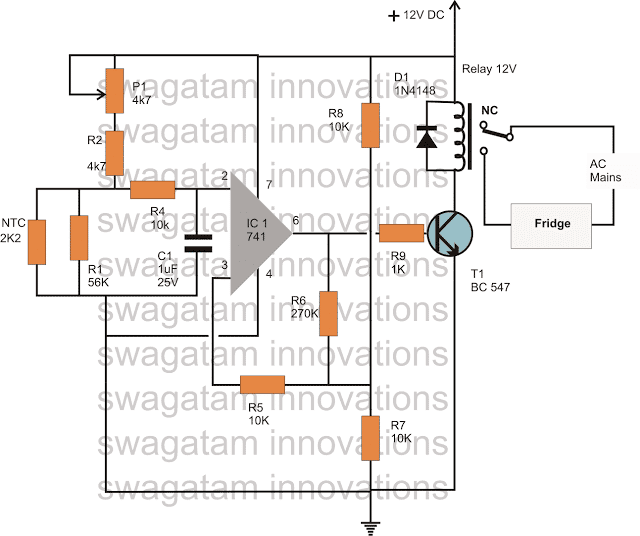
If you have any further questions regarding this automatic refrigerator temperature controller circuit, you can express the same through your comments.
Regulation RP1, RP2 can be temperature control preset points, 555 temporary Schmitt circuit inversion circuit using a relay to achieve automatic control.

| Updated 01 Apr 2018... Created by 29 Mar 2018 | |||||||||
A simple electronic thermostat with your own hands. I propose a method for making a homemade thermostat to maintain a comfortable room temperature in cold weather. The thermostat allows switching power up to 3.6 kW. The most important part of any amateur radio design is the enclosure. A beautiful and reliable case will ensure a long life for any homemade device. In the version of the thermostat shown below, a convenient small-sized case and all power electronics from an electronic timer sold in stores are used. The homemade electronic part is built on the LM311 comparator microcircuit.
Description of the operation of the circuit
The temperature sensor is a thermistor R1 with a nominal value of 150k, type MMT-1. Sensor R1 together with resistors R2, R3, R4 and R5 form a measuring bridge. Capacitors C1-C3 are installed to suppress interference. Variable resistor R3 balances the bridge, that is, sets the temperature.
If the temperature of the temperature sensor R1 drops below the set one, then its resistance will increase. The voltage at input 2 of the LM311 microcircuit will become greater than at input 3. The comparator will work and at its output 4 a high level will be established, a voltage applied to the timer electronic circuit through the HL1 LED will trigger the relay and turn on the heating device. At the same time, the HL1 LED will light up, indicating that heating is on. Resistor R6 creates negative feedback between output 7 and input 2. This allows you to set hysteresis, that is, the heating is turned on at a temperature lower than it is turned off. Power is supplied to the board from the electronic timer circuit. Resistor R1 placed on the ground requires careful isolation, since the power supply of the thermostat is transformerless and does not have a galvanic isolation from the mains, that is dangerous mains voltage is present on the device components... The manufacturing procedure for the thermostat and how the thermistor is insulated is shown below.
How to make a thermostat with your own hands
1. The donor of the case and the power circuit is opened - the electronic timer CDT-1G. A timer microcontroller is installed on a gray three-wire cable. We unsolder the cable from the board. The openings for the loop wires are marked (+) - +5 Volt power supply, (O) - control signal supply, (-) - minus power supply. An electromagnetic relay will switch the load.
2. Since the power supply of the circuit from the power unit does not have a galvanic isolation from the mains, then all work on checking and adjusting the circuit is carried out from a safe 5 volt power source. First, at the stand, we check the operability of the circuit elements.
3. After checking the circuit elements, the structure is assembled on the board. The board for the device was not designed and is assembled on a piece of a breadboard. After assembly, a performance check is also carried out at the stand.
4. Thermal sensor R1 is installed outside on the side surface of the block-socket housing, the conductors are insulated with a heat-shrinkable tube. To prevent contact with the sensor, but also to preserve the access of outside air to the sensor, a protective tube is installed on top. The tube is made from the middle part of a ballpoint pen. A hole has been cut in the tube for mounting on the sensor. The tube is glued to the body.
5. The variable resistor R3 is installed on the top cover of the case, and a hole for the LED is also made there. It is useful to cover the resistor case with a layer of electrical tape for safety.
6. The adjustment knob for the resistor R3 is homemade and made by hand from an old toothbrush of a suitable shape :).
Resistor R3Autonomous heating of a private house allows you to choose individual temperature modes, which is very comfortable and economical for residents. In order not to set a different mode in the room every time when the weather changes outside, you can use a thermostat or thermostat for heating, which can be installed on both radiators and the boiler.
Automatic regulation of heat in the room
What is it for
- The most common in the territory of the Russian Federation is , on gas boilers. But such, if one may say so, luxury is not available in all regions and localities. The reasons for this are the most commonplace - the lack of a CHP or central boiler houses, as well as gas pipelines nearby.
- Have you ever visited a residential building, pumping station or weather station far from densely populated areas during the winter, when the only means of communication is a sled with a diesel engine? In such situations, they very often arrange heating with their own hands using electricity.

- For small rooms, for example, one attendant's room at a pumping station is enough - it is enough for the most severe winter, but for a larger area, a heating boiler and a radiator system will already be required. To maintain the desired temperature in the boiler, we bring to your attention a homemade regulator.
Temperature sensor

- This design does not require thermistors or various sensors of the TCM type., here instead of them a bipolar ordinary transistor is involved. Like all semiconductor devices, its operation depends to a large extent on the environment, more precisely, on its temperature. As the temperature rises, the collector current increases, and this negatively affects the operation of the amplifier stage - the operating point shifts until the signal is distorted and the transistor simply does not respond to the input signal, that is, it stops working.

- Diodes are also semiconductors., and an increase in temperature has a negative effect on them too. At t25⁰C, the "continuity" of a free silicon diode will show 700mV, and for a permanent one - about 300mV, but if the temperature rises, then the forward voltage of the device will correspondingly decrease. So, when the temperature rises by 1⁰C, the voltage will decrease by 2mV, that is, -2mV / 1⁰C.

- This dependence of semiconductor devices allows them to be used as temperature sensors. On such a negative cascade property with a fixed base current, the whole circuit of the thermostat operation is based (diagram in the photo above).
- The temperature sensor is mounted on a VT1 transistor of the KT835B type, the load of the stage is resistor R1, and the mode of operation for direct current of the transistor is set by resistors R2 and R3. To keep the voltage across the transistor emitter at 6.8V at room temperature, the fixed bias is set by the resistor R3.
Advice. For this reason, R 3 is marked with a * on the diagram, and you should not achieve special accuracy here, as long as there are no large drops. These measurements can be made with respect to a transistor collector connected by a power supply to a common drive.
- Transistor p-n-p KT835B specially selected, its collector is connected to a metal case plate with a hole for attaching the semiconductor to the radiator. It is for this hole that the device is attached to the plate, to which the underwater wire is still attached.
- The assembled sensor is attached to the heating pipe using metal clamps, and the structure does not need to be insulated with any gasket from the heating pipe. The fact is that the collector is connected by one wire to the power source - this greatly simplifies the entire sensor and makes the contact better.
Comparator

- Comparator, mounted on the OP1 operational amplifier of the K140UD608 type, sets the temperature. The inverted input R5 is supplied with voltage from the emitter VT1, and through R6, the voltage from the engine R7 is supplied to the non-inverted input.
- This voltage determines the temperature to disconnect the load. The upper and lower ranges for setting the comparator threshold are set using R8 and R9. The required posteresis of the comparator operation is provided by R4.
Load management

- On VT2 and Rel1 made a load control device and the indicator of the operating mode of the thermostat is also here - red when heating, and green - reaching the required temperature. A diode VD1 is connected in parallel to the winding Rel1 to protect VT2 from the voltage caused by self-induction on the Rel1 coil when disconnected.
Advice. The figure above shows that the permissible switching current of the relay is 16A, which means that it allows the load to be controlled up to 3kW. Use a device with a power of 2-2.5kW to lighten the load.
Power Supply

- An arbitrary instruction allows for a real thermostat, in view of its low power, to use a cheap Chinese adapter as a power supply. You can also assemble a 12V rectifier yourself, with a circuit consumption current of no more than 200mA. For this purpose, a transformer with a power of up to 5W and an output from 15 to 17V will fit.
- The diode bridge is made on 1N4007 diodes, and the voltage regulator on the integral type 7812. Due to the low power, it is not required to install the stabilizer on the battery.
Adjusting the thermostat

- To test the sensor, you can use the most ordinary table lamp with a metal shade. As noted above, room temperature allows withstanding the voltage at the emitter VT1 of about 6.8V, but if you increase it to 90⁰C, then the voltage will drop to 5.99V. For measurements, you can use an ordinary Chinese multimeter with a DT838 thermocouple.
- The comparator works as follows: if the voltage of the temperature sensor at the inverting input is higher than the voltage at the non-inverting input, then at the output it will be equivalent to the voltage of the power supply - it will be a logical unit. Therefore VT2 opens and the relay turns on, moving the relay contacts to heating mode.
- Temperature sensor VT1 heats up as the heating circuit heats up and as the temperature rises, the voltage at the emitter decreases. At the moment when it drops slightly below the voltage that is set on the R7 engine, a logical zero is obtained, which leads to the transistor locking and the relay is turned off.
- At this time, the voltage is not supplied to the boiler and the system begins to cool down, which also entails the cooling of the VT1 sensor. This means that the voltage at the emitter rises and as soon as it crosses the border set by R7, the relay starts up again. This process will be repeated constantly.
- As you understand, the price of such a device is low, but it allows it to withstand the required temperature in any weather conditions. This is very convenient in cases where there are no permanent residents in the room who monitor the temperature regime, or when people are constantly replacing each other and, moreover, are busy with work.
The operation of a gas or electric boiler can be optimized by using the external control of the unit. Remote thermostats available on the market are intended for this purpose. This article will help you understand what these devices are and understand their varieties. It will also consider the question of how to assemble a thermostat with your own hands.
Purpose of thermostats
Any electric or gas boiler is equipped with a set of automation that monitors the heating of the coolant at the outlet of the unit and turns off the main burner when the set temperature is reached. Equipped with similar means and solid fuel boilers. They allow you to maintain the temperature of the water within certain limits, but nothing more.
In this case, climatic conditions indoors or outdoors are not taken into account. This is not very convenient, the homeowner has to constantly select the appropriate boiler operating mode on his own. The weather can change during the day, then it becomes hot or cool in the rooms. It would be much more convenient if the boiler automation was guided by the indoor air temperature.
To control the operation of the boilers depending on the actual temperature, various thermostats for heating are used. Being connected to the boiler electronics, such a relay turns off and starts heating, maintaining the required temperature of the air, not the coolant.
Types of thermal relays
A conventional thermostat is a small electronic unit mounted on a wall in a suitable location and connected to a heat source with wires. There is only a temperature regulator on the front panel, this is the cheapest type of device.

In addition to her, there are other types of thermal relays:
- programmable: they have a liquid crystal display, are connected using wires or use a wireless connection with the boiler. The program allows you to set the temperature change at certain hours of the day and on days during the week;
- the same device, only equipped with a GSM module;
- autonomous regulator powered by its own battery;
- wireless thermostat with a remote sensor for controlling the heating process depending on the ambient temperature.
Note. The model, where the sensor is located outside the building, provides weather-dependent regulation of the boiler plant operation. The method is considered the most effective, since the heat source reacts to changes in weather conditions even before they affect the temperature inside the building.
Multifunctional thermostats, which can be programmed, significantly save energy. In those hours of the day when there is no one at home, it makes no sense to maintain a high temperature in the rooms. Knowing the work schedule of his family, the homeowner can always program the temperature switch so that at certain hours the air temperature drops, and the heating is turned on an hour before the arrival of people.

Household thermostats equipped with a GSM module are capable of providing remote control of the boiler plant via cellular communication. The budget option is to send notifications and commands in the form of SMS messages from a mobile phone. Advanced versions of the devices have their own applications installed on the smartphone.
How to assemble a thermostat yourself?
Commercially available heating control devices are reliable enough and do not cause any complaints. But at the same time, they cost money, and this does not suit those homeowners who are at least a little versed in electrical engineering or electronics. After all, understanding how such a thermal relay should function, you can assemble and connect it to the heat generator with your own hands.
Of course, not everyone can make a complex programmable device. In addition, to assemble such a model, it is necessary to purchase components, the same microcontroller, digital display and other parts. If you are a new person in this business and understand the issue superficially, then you should start with some simple scheme, assemble and put it into operation. Having achieved a positive result, you can aim at something more serious.

First you need to have an idea of what elements a thermostat with temperature control should consist of. The answer to the question is given by the schematic diagram presented above and reflecting the algorithm of the device's operation. According to the scheme, any thermostat must have an element that measures the temperature and sends an electrical impulse to the processing unit. The task of the latter is to amplify or transform this signal in such a way that it serves as a command to the executive element - the relay. Further, we will present 2 simple schemes and explain their work in accordance with this algorithm, without resorting to specific terms.
Zener diode circuit
A zener diode is the same semiconductor diode that passes current in only one direction. The difference from a diode is that the zener diode has a control contact. While the set voltage is applied to it, the element is open and the current flows through the circuit. When its value falls below the limit, the chain is broken. The first option is a thermal relay circuit, where a zener diode plays the role of a logical control unit:

As you can see, the diagram is divided into two parts. On the left side, the part preceding the control contacts of the relay is shown (designation K1). Here, the measuring unit is a thermal resistor (R4), its resistance decreases with increasing ambient temperature. The manual temperature controller is a variable resistor R1, the circuit is powered by a voltage of 12 V. In normal mode, a voltage of more than 2.5 V is present on the control contact of the zener diode, the circuit is closed, the relay is on.
Advice. Any inexpensive commercially available device can serve as a 12 V power supply. Relay - reed switch brand RES55A or RES47, thermal resistor - KMT, MMT or the like.
As soon as the temperature rises above the set limit, the resistance of R4 drops, the voltage becomes less than 2.5 V, the zener diode will break the circuit. Next, the relay will do the same, turning off the power section, whose diagram is shown on the right. Here, a simple thermostat for the boiler is equipped with a D2 triac, which, together with the closing contacts of the relay, serves as an executive unit. The boiler supply voltage of 220 V passes through it.
Logic chip circuit
This circuit differs from the previous one in that instead of a zener diode, it uses a K561LA7 logic microcircuit. The temperature sensor is still a thermistor (designation - VDR1), only now the decision to close the circuit is made by the logic block of the microcircuit. By the way, the K561LA7 brand has been produced since Soviet times and costs mere pennies.

For the intermediate amplification of the pulses, the KT315 transistor is involved, for the same purpose, a second transistor, KT815, is installed in the final stage. This diagram corresponds to the left side of the previous one, the power unit is not shown here. As you might guess, it can be similar - with the KU208G triac. The operation of such a homemade thermostat has been tested on boilers ARISTON, BAXI, Don.

Conclusion
It is not difficult to independently connect the thermostat to the boiler; there are a lot of materials on this topic on the Internet. But making it with your own hands from scratch is not so easy, in addition, you need a voltage and current meter to make the adjustment. Buying a finished product or taking on its manufacture yourself - the decision is up to you.
I present an electronic development - a homemade thermostat for electric heating. The temperature for the heating system is set automatically based on the change in outdoor temperature. The thermostat does not need to be manually entered and changed to maintain the temperature in the heating system.
In the heating network, there are similar devices. For them, the ratio of the average daily temperatures and the diameter of the heating riser is clearly spelled out. Based on this data, the temperature for the heating system is set. I took this table of the heating network as a basis. Of course, some factors are unknown to me, the building may, for example, be not insulated. The heat loss of such a building will be large, the heating may be insufficient for normal heating of the premises. The thermostat has the ability to make adjustments for tabular data. (in addition, you can read the material at this link).
I planned to show a video of the thermostat in operation, with an eclectic boiler (25 kW) connected to the heating system. But as it turned out, the building for which all this was done was not residential for a long time, when checked, the heating system almost completely fell into disrepair. It is not known when everything will be restored, perhaps it will not be this year either. Since in real conditions I cannot adjust the thermostat and observe the dynamics of changing temperature processes, both in heating and on the street, I went the other way. For these purposes, I built a layout of the heating system.

The role of an electric boiler is played by a glass floor, a liter jar, the role of a heating element for water is a five hundred watt boiler. But with such a volume of water, this power was in excess. Therefore, the boiler was connected through a diode, reducing the power of the heater.
Connected in series, two aluminum flow-through radiators carry out heat extraction from the heating system, forming a kind of battery. With the help of a cooler, I create the dynamics of cooling of the heating system, since the program in the thermostat monitors the rate of rise and fall of the temperature in the heating system. On the return line, there is a digital temperature sensor T1, based on the readings of which the set temperature in the heating system is maintained.
In order for the heating system to start working, it is necessary for the T2 sensor (outdoor) to record a decrease in temperature, below + 10C. To simulate the change in outdoor temperature, I designed a mini refrigerator with a peltier element.
There is no point in describing the operation of the entire self-made installation, I filmed everything on video.

Some points about assembling an electronic device:
The electronics of the thermostat is located on two printed circuit boards; for viewing and printing, you will need SprintLaut program, not lower than version 6.0. The thermostat for heating is mounted on a din rail, thanks to the Z101 series housing, but something does not interfere with placing all the electronics in another housing of a suitable size, the main thing is that it suits you. The Z101 case does not have a window for the indicator, so you will have to mark and cut it yourself. The ratings of the radio components are shown in the diagram, except for the terminal blocks. To connect the wires, I used terminal blocks of the WJ950-9.5-02P series (9 pcs.), But they can be replaced with others, when choosing, take into account that the step between the legs coincides, and the height of the terminal block does not interfere with the housing being closed. The thermostat uses a microcontroller that needs to be programmed, of course, I also provide the firmware in the public domain (it may be necessary to modify it in the process). While flashing the microcontroller, set the internal clock generator of the microcontroller to 8 MHz.