How to make a microscope for soldering work. Homemade microscope Digital microscope in-house
I always loved biology, but I never had a microscope, and so I decided to get myself in order to admire the microcosm together with the younger generation, and it is possible to shoot the main chip of the 3DO console in between times.
It didn’t take long to choose the optical device itself, the choice fell on the Altami 104 microscope, this is a domestic microscope, my model with 2000x magnification (optics doesn’t give any more, no matter what they write there, it’s digital bullshit). Its price is very low, it cost me 12,800 rubles (May 2015). I don’t know how imported counterparts are, in comparison with it, but I’m happy as an elephant =) I doubt that it is possible to make the device any better for this money. I ordered it from the manufacturer, because it is faster and cheaper and probably more reliable: http://www.altami.ru.
Microscope Altami 104
For those who also did not find how to adjust the light field of the microscope, I suggest: remove the eyepiece (if you hurried to attach it), the diaphragm to a minimum and set the capacitor with the adjusting bolts so that the spot is in the center, then do not touch these screws anymore.
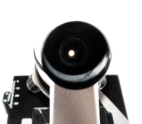
The spot to regulate
Of course, looking through a microscope (especially a monocular one) is hard and you want to display everything directly on the monitor. However, a microscope camera is comparable to the price of the microscope itself. And I decided not to take it yet, but to try to make it myself. What I will now tell you in all details =)
In addition to a microscope, you will need a webcam, preferably with a good matrix, I used a Logitech C270 (at one time I took several pieces for 700 rubles, a special camera for a microscope with a similar resolution costs 9000 rubles). It is very convenient in that the focus of this camera is adjusted mechanically, although for sure it is also possible in others - I just didn’t make it out, I don’t know.

Logitech C270 webcam
You will also need a screwdriver, a cork from a plastic bottle, a couple of small screws (five millimeters long), and it is also advisable to have a Glue Gun, a couple of ties and a drill similar to dentists =) So let's get started!
The first step is to reduce the weight of the camera, so you need to remove the camera mount. We pull out the end decorative plugs from the swivel mechanism and unscrew the screw, then we squeeze out the shaft and the camera becomes like a fluff.
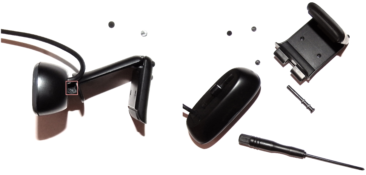
Parsing the fastening mechanism
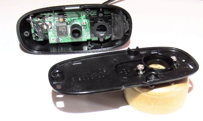
Next, you need to remove the front panel of the camera to get to the focus setting. To do this, you need to pull off the decorative panel, and then unscrew a couple of screws and remove the main plastic panel, behind which there is a simple filling.

Opening the camera
Now we need an eyepiece attachment, and an ordinary plastic bottle cork will play its role! It ideally fits in diameter and inside it has a stop so that it does not snuggle close to the optics - you can't imagine better, you just need to cut the thread and drill a hole with a radius of 3 plus or minus a millimeter. For this I used a drill with a flexible liner, as a nozzle I used a small drill. If you don't have this on your farm, take an ordinary knife and carefully cut the thread, and make the hole with a regular drill, or even dig it. The pieces of plastic can be scorched with fire so that they do not dangle, then the top of the cork must be leveled, for example, with a stone.

Cork preparation
Place the finished plug on the eyepiece and lean the camera with the main panel on, if necessary, adjust the focus (slowly, slowly, as accurately as possible). And also, cover the LED in the camera, for example, with electrical tape, so that it does not shine where it is not necessary.
Next, you need to screw the main panel of the camera to the cork, for this I used screws, you can probably put it on the glue, but you need to accurately position the camera, so the screws are preferable, first put one in, maybe not the first time. Try it on, it is possible to adjust it relative to the first screw and only then fix it with the second. If the slope is not optimal, insert spacers made of pieces of plastic, or something that is at hand. Then complete a general fitting.
Fastening the panel to the cork
Now it remains to fix the result, for this you can use a glue gun. Here I recommend glueing a tie or other flexible piece of plastic as clamps, this is necessary in order to fix the eyepiece so that the image does not rotate, following the webcam wire, you can even have several such ties, well, or whatever you think of. Pour glue around and allow to cure.

Complete digital attachment
Now we will install all this on the eyepiece of the microscope, tighten the clamp to the eyepiece tube with a coupler, and enjoy the microworld! The whole process takes no more than an hour, it took longer to write an article.

Microscope assembly
In general, I must say that a special attachment is preferable, since it does not try to adapt to the illumination, which, under some operating parameters of the microscope, leads to auto-tuning bounce in the image, perhaps this is regulated in webcams, I have not figured it out yet. And everything is calibrated exactly on the factory attachments, without any screws. But nevertheless, for amateurs, the result is very nothing, although the drug was hastily done on old glass with dirty hands - that's why there is so much garbage in the picture =)

Some kind of bacteria on onion cells
As a user of windows 7, after XP an unpleasant surprise awaited me - in 7 they removed the webcams from "my computer", i.e. There are no regular means to look at the result, so it was not without programming =) Unpack it to any place and run the executable.
We propose to create at home an electronic YUSB microscope of medium resolution for connecting to a computer via a USB cable. You may already have the necessary parts to complete this project, otherwise you will have to buy them.


The necessary parts for assembling a homemade microscope with your own hands:
- One white LED.
- Wire with a cross section of 0.05 mm2.
- Heat shrink tubing or electrical tape.
- Glue gun (or any other suitable glue).
Step 1: modify the device


The pocket microscope has a built-in incandescent lamp for illumination, which is powered by two AAA 1.5V batteries. Remove the lamp and batteries from the housing and install one white LED by running the wires from it inside the housing to the top of the microscope.
Use heat shrink tubing or electrical tape to insulate the contacts.
Check the operation of the LED with a battery and mark which wire is the anode and which is the cathode.
There is a small but damn bright orange LED on the camera board. Remove it carefully and solder the wires from the white LED in its place. The LED is software controlled, USB will provide power to the camera and LED. Make sure the wires are free of tension.
Do not feel sorry for hot glue for gluing the white LED to the inside of the case. Position the LED so that it illuminates where the lens is pointing.
Step 2: remove the plastic case from the camera

You do not need to remove the case, but it is better to remove it anyway.
There is a single locking screw under the shiny logo on the case.
Step 3: assembling


Assemble the case.
Remove the small rubber ring from the eyepiece and insert the camera into the eyepiece.
Apply some glue around the junction of the camera lens and the microscope eyepiece.
Step 4: make the base


The finished USB microscope is light enough to be held in an upright position. Glue a couple of neodymium magnets to the bottom of the microscope. Then make a wooden base with a small metal plate glued to it.
The idea is that a microscope, magnetized to a metal plate, can freely slide along it when moved by its hand and remains stationary if not touched.
Step 5: take photomicrographs


Above are some photographs taken with this microscope. You can see how the microscope magnifies various objects.
See how, when zoomed in, a portion of the memory core from an old CDC-6600 computer looks like.
The left photo shows the board itself, and the right photo shows a close-up of the toroids and wire mesh that make up the memory cells.
Since the camera has a 2MP resolution, it has pretty good image quality. The ZEISS camera lens has an electromechanical body and, through software, adjusts to the focal length that we have created for it.
The simplest electronic digital microscope can be made with your own hands using an old phone with a camera, although it is still better to use a smartphone (in our case, an iphone) and the screen is larger and the camera is better.
The total magnification of the microscope can be up to 375 times, depending on the number and class of lenses used.
By the way, during the manufacture of microscopes, we took the lenses themselves from an old laser pointer, but if you do not have one, you can buy them cheaply in any Chinese online store.
The cost of a homemade microscope does not exceed 300 rubles, if we take into account the cost of materials:
Materials for making
A complete list of required materials for the project:

Manufacturing
1) Disassembling the laser pointer and removing the lens.
For this we use the cheapest pointer, so do not buy expensive models for this. A total of 2 lenses are required. (You can skip this step if you buy the lens itself from the store.)
To disassemble the pointer, unscrew the back cover and take out the batteries. We extract all the insides using a simple pencil with an eraser. The lens is in the lens, and to get it you need to unscrew a piece of small black plastic.


The lens itself consists of a thin translucent glass, about 1 mm thick, you can attach it to the phone's camera to experiment with an enlarged photo, it is very difficult to take a high-quality photograph, so I decided to make a fixer stand for the microscope.


2) Manufacturing the base of the case.
The entrance went to a piece of plywood measuring 7 x 7 cm, in which we drill 3 holes for the posts (bolts) The places for drilling holes are shown in the photo with marks.


3) Preparation of plexiglass and lenses.
Cut out 2 pieces of plexiglass with dimensions: 7 x 7 cm and 3 x 7 cm. Drill 3 holes on the first piece of plexiglass according to the plywood pattern, this will be the upper part of the case. On the 2nd piece we drill 2 holes according to the plywood pattern, this will be the intermediate shelf of the microscope.
Do not press hard when drilling in Plexiglas.


Now you need to drill holes in the plexiglass for the lens and objective, this requires a D = D lens drill or slightly less. Finish adjusting the hole using round files or rasps.
The lenses must be embedded in the drilled hole in both glasses.
4) Assembly of the case.
When all the parts of the microscope are ready, you can proceed to the assembly itself, but before that there is still 1 moment left:
- it is necessary to supply a light source from below, for this I drilled a hole in the lower part of the case for mounting a small diode lamp.


We proceed to the final assembly. We tighten the bolts tightly to the base.
The intermediate microscope stand with the o 2 lens must be placed up and down so that the magnification size of the optics can be adjusted.


To do this, we tighten the wing nuts, 2 washers by 2 bolts and mount the glass with the already glued-in lens measuring 3 * 7 cm.


Then we install the top cover, here we are already using the usual nuts, but we put them on top and bottom.


Congratulations, you just made a cheap digital microscope, here are some pictures taken with it.


Video instructions for making and demonstration of work
(in English)
Due to the crazy pace of development of radio engineering and electronics in the direction of miniaturization, more and more often when repairing equipment you have to deal with SMD radio components, which, sometimes, cannot even be considered without increasing, not to mention careful installation and dismantling.
So, life made me look for a device on the Internet, such as a microscope, which could be made by hand. The choice fell on USB microscopes, which are offered a lot of homemade products, but all of them cannot be used for soldering, because have a very small focal length.
I decided to experiment with optics and make a USB microscope that would suit my needs.
Here is his photo:

The design turned out to be rather complicated, therefore, it makes no sense to describe in detail each manufacturing step, since this will greatly clutter the article. I will describe the main units and their step-by-step production.
So, “without spreading our thoughts along the tree”, let's start:
1. I took the cheapest A4Tech webcam, to be honest, they just gave it to me because of the fig quality of the image, which I didn't give a damn about, as long as it was in good working order. Of course, if I took a better and, naturally, expensive webcam, the microscope would have turned out with better image quality, but I, like Samodelkin, act according to the rule - "For lack of a maid, they" love "a janitor", and besides however, the image quality of my USB soldering microscope was fine.


I took the new optics from some children's telescopic sight.


To mount the optics in a bronze bushing, I drilled two holes ø 1.5 mm in it (bushing) and tapped an M2 thread.

I screwed M2 bolts into the threaded holes, on the ends of which I glued beads for the convenience of unscrewing and twisting, in order to change the position of the optics relative to the pixel matrix in order to increase or decrease the focal length of my USB microscope.


Next, I thought about highlighting.
Of course, it was possible to make LED backlighting, for example, from a gas lighter with a flashlight, which costs a penny, or from something else with an autonomous power supply, but I decided not to clutter up the structure and use the power of the webcam, which is supplied via a USB cable from a computer. ...
To power the future backlight, from the USB cable that connects the webcam to the computer, I brought out two wires with a mini-connector (dad) - "+ 5v, from the red wire of the USB cable" and "-5v, from the black wire."


To minimize the design of the backlighting, I decided to use LED-LEDs, which were removed from the LED-backlight tape from the broken matrix of the laptop, fortunately, I had such a tape in the "store" for a long time.

Using scissors, a suitable drill and a file, a ring of the desired size made of double-sided foil-clad fiberglass was made and, on one side of the ring, the paths for soldering LED-LEDs and quenching SMD resistors with a nominal value of 150 ohm were cut out (I put a 150 ohm resistor ) soldered our backlight. To connect the power supply from the inside of the ring, I soldered a mini-connector (mother).


To connect the backlight to the lens, I used (not used for attaching the lens glass) a round threaded nut, which I soldered to the inside of the backlight ring (that's why I took double-sided fiberglass).

So, the electro-optical part of the USB microscope is ready.


Now you need to think about the movable mechanism for fine-tuning the sharpness, the movable tripod, the base and the work table.
In general, it remains to come up with and create the mechanical part of our homemade product.
Go…
2. As a movable mechanism for fine-tuning the sharpness, I decided to take an outdated mechanism for reading floppy disks (people called it "floppy drive").
For those who have not seen this "miracle of technology", it looks like this:


In short, after a complete disassembly of this mechanism, I took the part that was responsible for the movement of the read head, and, after mechanical revision (trimming, cutting and filing), this is what happened:


To move the head in the floppy drive, a micromotor was used, which I disassembled and took only the shaft from it, fixing it back to the movable mechanism. For the convenience of rotation of the shaft, on its end, which was inside the engine housing, I put on a roller from the scroller of an old computer mouse.
Everything turned out as I wanted, the movement of the mechanism was smooth and precise (no backlash). The movement of the mechanism was 17 mm, which is ideal for fine-tuning the sharpness of the microscope at any focal length of the optics.
Using two M2 bolts, I fixed the electron-optical part of the USB microscope to the movable mechanism for fine-tuning the sharpness.


The creation of a movable tripod did not cause any particular difficulties for me.
3. Since the times of the USSR, I had an UPA-63M enlarger in my shed, the details of which I decided to use. For the tripod stand, I took just such a ready-made rod with a mount, which was included in the kit of the magnifier. This rod is made of an aluminum tube with an outer ø 12 mm and an inner ø 9.8 mm. To attach it to the base, I took an M10 bolt, screwed it to a depth of 20 mm (with force) into the bar, and left the rest of the thread by cutting off the bolt head.


The mount had to be slightly modified in order to connect it with the microscope parts prepared in step 2. To do this, I bent the end of the mount (in the photo) at a right angle and drilled a ø 5.0 mm hole in the bent part.


Then everything is simple - with an M5 bolt 45 mm long through the nuts, we connect the pre-assembled part with the mount and put it on the rack, securing it with a locking screw.


Now the base and the table.
4. For a long time I had a piece of translucent light brown plastic. At first I thought it was plexiglass, but during processing I realized that it was not. Well, okay - I decided to use it for the base and stage of my USB microscope.

Based on the dimensions of the previously obtained structure, and the desire to make a large table for reliable fastening of the boards when soldering, I cut out a rectangle of 250x160 mm from the existing plastic, drilled a hole ø 8.5 mm in it and cut an M10 thread for attaching the rod, as well as holes for fixing the table base.


I glued the legs to the bottom of the base, which I cut out from the soles of old shoes with a homemade drill.

5. I turned the table on a lathe (at my former enterprise, of course, I do not have a lathe, although there is a 5th grade of a turner) 160 mm in size.

As a base for the table, I took a stand for leveling the furniture relative to the floor, it fits perfectly in size and looks presentable, besides, it was presented to me by a friend who has this fittings, "like a fool's makhorka."
I came across an interesting note on how to make a microscope out of a smartphone on the Internet. The process in it was described in great detail and in an accessible way - the author was really well versed in what he was writing about. I even wanted to read the rest of his notes. But what a disappointment befell me when I discovered that the note was translated and borrowed from a German site.
Among the creative intelligentsia, the borrowing of ideas is not particularly condemned. So I wanted to repeat the foreign experience and write more detailed material. It is not difficult to repeat the design of a smartphone table. The table can be made in one evening, if you stock up on everything you need.
Four M8 x 100 mm bolts, M8 nuts and a pair of "lambs" were bought in the nearest utility room.
Turning a smartphone into a microscope is very simple: you need to put a small lens on the camera lens. The lens can be removed from an old CD drive or from a laser pointer purchased from a local kiosk. But when you attach the lens to your smartphone. then you will face one problem: it is very difficult to keep the smartphone exactly at a short distance from the subject due to the shallow depth of field. This is where you need to start making a special table.
The base of the table is made of 20 mm thick trim boards. In the corners, holes are drilled for bolts with a diameter of 8 mm. I got 3 mm plexiglass at work - I borrowed a stationery stand. From it I cut out a cover for the table, on which there will be
lie smartphone. Just like in the base, holes for bolts are drilled in the cover. A subject table was cut out of the same stand to place the objects of study.
We fix the lid. It rests on four nuts and is fixed with nuts from above.
We insert the bolts into the holes in the base. Their heads will be the legs of the table.
We fix the bolts with nuts.
Now we set up the stage. The table rests on two lambs, they also adjust its height.
A hole is drilled under the lens in the cover. Even two, since I managed to find two different lenses. The hole is drilled with a diameter smaller than the diameter of the lens, and then bored with a round file to the desired size. The place for the hole for the lens must be chosen by placing the smartphone against the cover and marking the position of the camera lens with a felt-tip pen.
We make the hole conical (it tapers downward) - then the lens fits into the hole and does not fall through. There is no need to fix the lens.
Visually, the scrapbooking glass gives a very decent magnification.
Last year I ordered different glasses for caskets for Ali. A bag with 20 transparent cabochons with a diameter of mm cost about a dollar. This cabochon was used as a lens.
Poppy flower, stamens. Shooting in the sun without a table, hand-held. The magnification estimate is 30 ... 40x.
The first object of research is a banknote. We fix the hundred-ruble on the subject table. We combine the lens with the lens, turn on the camera mode and put the smartphone on the cover. Then, with the help of the lambs, we adjust the position of the stage, trying to achieve the maximum sharpness of the image.
One-ruble bill. The picture turned out to be quite clear, the image was slightly blurred only at the edges. The magnification estimate is 30 ... 40x.
Dandelion under the microscope. Shooting without a table, with a hand. The magnification estimate is 30, .. 40x.
OWN HAND LASER POINT LENS
I still wanted to improve the quality of the microcosm images. "Probably, if you use a real lens, the image will be better." - I thought. On the way home from work, I bought a laser pointer at a newsstand for 150 rubles.
Micro font on a 500-ruble note: the image was slightly blurred at the edges. The magnification estimate is 60 ... 80x.
Fine river sand. A very beautiful picture turned out!
I disassembled the device and got a small lens. A soft pad from the pointer also came in handy.
The lens with the gasket fits perfectly into the place of the cabochon. It remains only to combine the camera lens with it. Surprisingly, the smartphone itself focuses the lens, taking into account another optical element. How he does it remains a mystery to me.
Experimenting with the cabochon. I completely forgot that a good microscope should have a standard illumination. The better the subject is lit, the better the picture will be. This is where the powerful LED flashlight from the survival kit came in handy. By changing the angle of illumination of the object, I achieved a sharper image.
Fragments of a mosquito that wanted to bite me. Shooting in reflected light, magnification rating - 60 ... 80x.
Afterword
Make a microscope in the country - open a window to the microcosm for children! Perhaps this experience will determine their future specialty.
MICROSCOPE FROM THE PHONE WITH YOUR OWN HANDS - VIDEO IN HOME
 Fashion Men Sunglasses by Kdeam Polarized Men Classic Sunglasses ...
RUB 541.41
Free shipping