Production of multilayer printed circuit boards at home. Production of printed circuit boards
Andreev S.
At home, you can make printed circuit boards. In terms of quality, practically no inferior to the factory manufacture. Observing a certain procedure, you will be able to repeat it for your homemade.
First you need to prepare a picture of printed tracks. How to breed a printed fee here will not be discussed, suppose that the drawing already has, taken from the magazine, the Internet, or is drawn by you personally or with the help of a special program. Preparation of the drawing depends on what way it is supposed to apply a picture of the printed paths on the workpiece. Three ways are now most popular - manual drawing with the help of an immentable marker, the laser iron method and photo exposure to the photoresist.
First method
The first method is suitable for simple boards. Here, the final point of preparation of the drawing should be an image on paper on a scale of 1: 1, view of the tracks. Well, if there is already a paper image 1: 1, for example, in the magazine "Radio constructor", mostly all fees 1: 1. But in other publications and especially on the Internet there is not everything is so smooth.
If there is a paper image on a different scale, it must be increased accordingly or reduce, for example, using copying on a xerox with scaling. Either scan to the computer to the graphics file and in some graphic editor (for example, in Adobe Photoshop) to bring dimensions to 1: 1 and print on the printer. The same applies to the drawings of boards obtained from the Internet.
So, paper Figure 1: 1 View from the side of the tracks. We take a blank from a foil glassstolite, slightly sanding a foil "zero", we put a paper drawing on the workpiece, we attach it to not moved, for example, a tape tape. And sheer or toll pierce paper at points where there should be holes, and so that it remains clearly visible, but a shallow trail on the foil.
The next stage, - remove the paper from the workpiece. In the marked places drill the holes of the required diameter. Then, looking at the drawing of the tracks, draw the insanible marker of the printed tracks and mounting sites. We begin to draw from the mounting sites, and then connect them with lines. Where the thick lines are needed by a marker several times. Or draw the contour of the thick line, and then tightly painted inside. Tracy Consider later.
Second way
The second method of the radio amateurs called the "laser irrigation". The method is popular, but very capricious. Required tools - a laser printer with a fresh cartridge (a tired cartridge, in my experience, is not at all suitable for this case), the household iron iron, very tricky paper.
So, the preparation of the picture. The drawing should be black (without halftone, color), on the scale of 1: 1, and moreover, it should be in the mirror image. In total, you can achieve the processing of drawing on a PC in some graphic editor. The above Adobe Photoshop is quite conspicuous, although even the simplest Paint program from the standard Windows set allows you to make a mirror image.
The drawing preparation result should be a graphic file with an image on a scale of 1: 1, black and white, without halftone and color, which can be printed on the laser printer.

Another question is, important and thin, - about paper. The paper should be dense and at the same time thin, the so-called, coated (the usual "for xerox" does not give good results). Where to take it? This is the main question. On sale it is only fat - for photos. And we need thin. Look in the mailbox! Many advertising booklets are made on such paper, - thin, smooth, glossy. For the presence of color pictures, you do not pay attention, - they will not interfere with us. However, no, if the seal is made poorly, that is, the pictures are dirty fingers, - such advertising products will not suit us.
Next, print your file on this paper and look what happened. As I said above, the printer must be with a fresh cartridge (and a drum if the drum is separate from the cartridge). In the field settings, you need to select the print mode with the highest print density, in different printers this mode is called differently, for example, "brightness", "DARK", "contrast". And no economical or draft (in the sense, "Chernovik") modes.
All this is necessary as you need a dense and uniform pattern, with paths depicted a sufficient thick layer of toner without interrupts, light strips that can be when working with a worn drum cartridge. Otherwise, the drawing will be uneven along the thickness of the toner and this will result in the finished board in these places there will be interruption of tracks.
We print the drawing, cut out with scissors so that it was a bit along the edges of superfluous, we put the drawing on the workpiece with toner to the foil, and you clutch your more unnecessary under the fee so that these parts are pressed by the board lying on the table and did not give the picture to move. We take the usual iron without sweeping warming it to the maximum temperature. Smoothly smooth, not allowing drawing offsers.
Do not overdo it, since the toner will smear from excessive pressure and some tracks are alive. The poorly processed edges of the workpiece will not allow well to smooth the toner to the workpiece.
In general, the essence of the process is that the toner of the laser printer melts and sticks to the foil when molting. Now we wait until the billet cools. How to cool down the minutes by 10-15 in the dishes with warm water. The coated paper softened and begins to lag behind the board. If the paper does not lag behind, carefully trying to roll down the paper with your fingers under the jet of water.
On the workpiece will be visited by a thin layer of shaggy paper. Strongly try to roll all the paper is not necessary, as you can contemporary and tuner from foil. It is important that the papers are not hanging, and there should be no paper between the tracks at all.
Third way
Third way, - photo exposure on a layer of photoresist. Photoresist is sold in radio components stores. Usually an instruction is attached. Following this instruction, you need to apply a photoresist on the workpiece, and when it will be ready to expand on it a drawing of the board layout. Then to be treated with a special solution - developer. Lighted areas will be cleaned, and the film will remain on the unlit.
The drawing must be prepared as well as for a "laser iron", but you need to print on a transparent film for the printer. This film is applied to the workpiece treated with a photoresist (toner to the workpiece) and exhibit according to the instructions. This method is complex, requires a photoresist, manifesting a solution and strictly complying with the instruction, but it allows you to get a wiring of almost factory quality.
In addition, the printer does not have to be laser, and inkjet is suitable, provided that you will print on a transparent film for inkjet printers. Exposing the film always needs to be applied to the workpiece to which toner, press glass for the smallery. If the fit will be loosely, or put the film with the other side. The image will be intelligible as the tracks are vague due to the violation of the focus.
Package etching
Now about etching. Despite the many alternative ways of etching the most efficiently old good "chlorine iron". It was not enough to get it before, and now it is sold in jars in almost any radio component store.

It is necessary to make a solution of chlorine iron, on the jar usually there is an instruction how many contents of the jar for how much water. Practically it turns out on a glass of water four teaspoons with a hill powder. Mix well. At the same time, strong heat dissipation may occur and even boiling on the surface and occur splashing, so act carefully.
We stretch the most convenient in the bath for photo printing, but it is possible in an ordinary ceramic plate (in a metal bowl it is impossible in any way!). The fee must be located paths down and being in suspended. I simply put in a plate or a bath four small, specially prepared with a file fragment of an ordinary building bricks, so that the board lay the corners on them.
Now it remains only to pour the solution into this container and gently put a fee on these backups. Some prefer to lay a fee on the surface of the solution so that it holds the surface tension of the water, but I do not like such a way because the board is heavier than water and with any little concussion will pick up.
Depending on the concentration and temperature of the solution, the blending occupies from 10 minutes to 1 hour. To speed up the etching process, you can create vibration, for example, to put a working electric motor near the table. And it is possible to warm the solution with a conventional incandescent lamp (putting a bath under the table lamp).
It should be noted that the remnants of the chalk (from the coated paper) on toner take into a reaction with a solution of chlorine iron, bubbles are formed that prevent the etching. In this case, you need to periodically remove the fee and rinse with water.
In addition to the most convenient and effective in my opinion, there are other options in a solution of chlorine iron. For example, etching in nitric acid. The etching occurs very quickly, and with the release of heat. A solution of nitric acid should be a concentration of no more than 20%. After etching to neutralize the acid, it is necessary to flush with a solution with a solution of drinking soda.
The method gives rapid etching, but has many drawbacks. First, if the workpiece can be a little distinguished by strong swells of the tracks. And secondly, this is the most important way very dangerous to health. In addition to the fact that nitric acid itself can cause chemical burns when entering the skin, it also distinguishes poisonous gas - nitrogen oxide. So I do not recommend this method.
Another method is etching in a solution of a mixture of copper sulfate and cook salt. This method was actively used in "up to perestroika times" when the chlorine iron, as much more, was absent in the free sale, but fertilizers for the garden were relatively available.
The sequence of making a solution is as follows, - first pour into a bath from plastic or glass, ceramics water. Then pushing the cook salt at the rate of two tablespoons on a glass of water. Stir the non-metallic wand until the salt is completely dissolved, and add copper vigor from the calculation - one tablespoon on a glass of water. Stir again. Immerse yourself in a solution fee.
In fact, etching occurs in the cooking salt, and the copper vigor works as a catalyst. The main disadvantage of this method is a very long etching, which can be from a few hours and reach the day. Slightly accelerate the process can be heated to 60-70 ° C. It often turns out that one portion is not enough for the entire fee and the solution has to pour and prepare again and again. This method in all parameters is inferior to etching in the chlorine gland, and it can only be recommended if the chlorine iron cannot be purchased.
Etching in electrolyte for car batteries. The electrolyte of the standard density must be diluted with water one and a half times. Then add 5-6 pills of hydrogen peroxide. The etching occurs in speed is about the same as in the solution of chlorine iron, but there are all the same disadvantages as when etching in nitric acid, since the electrolyte is an aqueous solution of sulfuric acid. Entering the skin leads to burns, in the process of etching, poisonous gas is distinguished.
After etching, you need to remove the paint, a photoresist or toner from the surface of the printed tracks. The drawing with a marker is easily removed by almost any solvent for paints, or alcohol, gasoline, cologne. Photoresist can be removed by White alcohol or acetone. But the toner is the most resistant to chemistry material. It only takes it mechanically. At the same time, it is necessary not to damage the tracks themselves.
Cleaned from paint (toner, photoresist) The workpiece must be rinsed with water, dry and go to drilling holes. The drill diameter depends on the diameter of the desired hole. Drills - for metal.

To verify me personally conveniently with a compact accumulator-screwdriver. At the same time, I have a vertically, having screwed it with screws to a wooden bar fixed in the vice. Drill moving horizontally leaning hand on the table. But the small drilling machine will certainly be better. Many use miniature boots for engraving, but I have no such equipment.
By the way, you can feed the drill-screwdriver from the laboratory power supply, after removing the battery, feeding the voltage directly to the contacts ("crocodiles"). It is convenient that without a battery drill is much easier, well, plus the battery does not discharge or you can use a tool with a faulty battery.
Well, the board and ready.
Many say that it is very difficult to make your first printed circuit board, but in fact it is very simple.
Now I will tell a couple of famous ways, how to make a printed circuit board at home.
To start a short plan, how the printed circuit board is manufactured:
1. Preparation to the manufacture
2. Conducting tracks
2.1RI for lacquer
2.2Ris the marker or nitrocra
2.3 Labeling Iron
2.4 Street with film photoresist
3. Placerave
3.1 Praising by chlorine iron
3.2 Creating copper sulfate with salt salt
4. Support
5. Screw
1. Preparation for the manufacture of printed circuit board
To begin with, we will need a sheet of foil textolite, metal scissors or a metal hacksaw, a plain grater for pencils and acetone.
Gently cut out the necessary piece of foil textolite. Then it is necessary to clean the neatly our textolite, from the copper side, a grater for a pencil to shine, then wipe our workpiece with acetone (this is done for degreasing).

Figure 1. Here is my billet
Everything is ready, now do not touch the brilliant side, otherwise you have to degrease.
2. Draw conductive tracks
These are the tracks by which the current will be held.
2.1 Draw tracks with varnish.
This method of the most longtime and sahama is simple. We will need the easiest nail polish.
Correctly draw nail polished track conductive tracks. Be careful because the lacquer sometimes breaks down and the tracks merge. Let's give a lacquer. That's all.

Figure 2. Laccusted tracks
2.2 Draw tracks by a nitrocrase or marker
This method is no different from the previous one, only draws everything much easier and faster

Figure 3. Tracks, drawn nitrocra
2.3 Laser Ironing
Laser iron One of the most common ways to make printed circuit boards. The method is not time consuming and takes little time. I personally did not try this way, but many familiar use it with great success
To begin with, we need to print a drawing of our printed circuit board on the laser printer. If there is no laser printer, you can print on the jet, and then make copies on a xerox for drawings, I use the Sprint-Layout 4.0 program. Just when printing, be careful using the mirror, many more than once killed the fees in this way.
We will print on some old unnecessary magazine with glossy paper. Before printing, adjust your printer to the maximum toner consumption, it will save from many problems.

Figure 4. Printing drawing on glossy magazine paper
Now take out our drawing in the form of an envelope.

Figure 5. Envelope with a scheme
Now we put our workpiece into the envelope and carefully we pull it out behind the scotch. We stick so that the textolite either moved in the envelope

Figure 6. Ready Envelope
Now weep the envelope. We try not to miss a single millimeter. The quality of the board depends on it.

Figure 7. Ironing board
When the iron will be finished, carefully false envelope in the dishes with warm water

Figure 8. Matching the envelope
When the host envelope, roll the paper without sharp movements to damage the toner tracks. If there are defects, take a CD or DVD disk marker, and correct the tracks.

Figure 9. Almost ready
2.4 Production of a printed circuit board with a film photoresist
As in the previous way, we make a drawing using the Sprint-Layout 4.0 program and press print. We will print on a special film for printing on inkjet printers. Therefore, we set up printing: remove the parties F1, M1, M2; In the options, put the tick negative and frame.

Figure 10. Print Setup
Configure the printer to black and white printing and set the maximum intensity in the colors setting.

Figure 11. Setting up printer
We print on the matte face. This side is working, it is possible to determine it by sticking it to the fingers.
After printing, our template is lying to dry.

Figure 12. Such our template
Now cut off the piece of film photoresist

Figure 13. Photoresist film
Carefully remove the protective film (it is matte), we glue it to our collection of textolite

Figure 14. glue to textolite photoresist
It is necessary to glue carefully, and remember, the better you press the photoresist, the better the tracks on the board. That's about what should happen.

Figure 15. Photoresist on textolite
Now from the film on which we printed, cut out our drawing and apply it to our photoresist with textolite. Do not confuse the parties, and then the mirror will turn out. And cover the glass

Figure 16. We apply the film with the drawing and cover with glass
Now we take the ultraviolet lamp and extinguish our tracks. For each lamp, your own parameters for manifestation. Therefore, the distance to the board and the luminescence time choose themselves

Figure 17. Introduce the path of the ultraviolet lamp
When the tracks were lit, we take a small plastic dishes make a solution of 250 grams of water spoon of soda and lower our fee already without the template of our board and the second transparent film of the photoresist.

Figure 18. Fallen fee in soda solution
In 30 seconds, our stamp is manifested. When the dissolution of the photoresist ended, our fee will be turned out, which they wanted. We rinse thoroughly under the jet of water. All is ready

Figure 19. Finished fee
3. etching a new printed circuit board. Etching is a way to remove excess copper from the textolite.
For etching, special solutions are used, which are made in plastic dishes.
After the manufacture of the solution, the printed circuit board is lowered there and deteriorates during a certain time. You can speed up the etching time by maintaining the temperature of the solution in the area of \u200b\u200b50-60 degrees and constant stirring.
Do not forget to use rubber gloves when working, and then wash your hands well with soap.
After the fee drive, it is necessary to rinse well under water and remove the residues of the varnish (paint, photoresist) by conventional acetone or lacquer removal fluid.
Now a little about solutions
3.1 Herbal iron
One of the most famous methods of etching. For etching is a chlorine iron and water with a ratio of 1: 4. Where 1 is a chlorine iron, 4 - water.
It is simply prepared: the desired amount of chlorinated iron is poured into the dishes and is filled with warm water. The solution should turn out green.
The time of etching board of size 3x4 centimeters, in the area of \u200b\u200b15 min
You can get a chlorine iron on the market or in radio electronics stores.
3.2 Pasteing with copper vigor
This method is not as common as the previous one, but also meets often. I personally use this way. This method is much cheaper than the previous one, and get the components easier.
In the dishes we fall asleep 3 spoons of the dining room salt, 1 spoonful of copper sulfate and fill with water 250 grams with a temperature of 70 degrees. If everything is right, the solution should become turquoise, but a little climbing green. To accelerate the process, it is necessary to mix the solution.
Etching time of 3x4 centimeters size, in the area of \u200b\u200bone hour
Get copper vigoros can be in stores agricultural products. Copper cunery is a blue fertilizer. It has a form of crystal powder. ACB protection device from full discharge
Hello dear visitor. I know why you read this article. Yes, yes I know. No What are you? I am not a telepath, I just know why you got on this page. Surely ......
And again my friend Vyacheslav (Saxon_1996) wants to share his work on the columns. The word Vyacheslav went to somehow one column 10mas with a filter and a high-frequency speaker. I'm not long .......
The Radio Technology for the manufacture of printed circuit boards at home consists of several stages.
-
Drawing the drawing using a laser printer.
Drawing pattern.
Solution for etching.
Etching.
Preparing the drawings of the printed circuit board.
Manually conveniently performing a drawing of a printed circuit board on a scale of 1: 1 on paper from the checkers (has a cell with a side of 2.5 mm, in the "Silent" of the chip), if there is no one, then you can "open" school paper "into a cell" with a decrease in 2 In the most extreme case, you can use the usual millimeter. The pathways from the soldering should be drawing with solid lines, and the tracks from the part side (in the case of two-way installation) draw dashed lines. It should be noted that the disposable elements must be in mirror reflection. The centers of the elements legs are marked with points around which it is necessary to draw a platform area. For follow-up, it is very important that the size you choose the installation sites for items (it's a shame when when drawing a "live" or track between the playgrounds does not pass, or after soldering, the elements fall out with the players). The width of the tracks should be chosen on the basis of what you will draw a fee when using glass raysfederes about 1.5 mm. After the drawing is ready, you need to apply the drawing to the luminous surface (for example, the window of the window) with the opposite side to yourself and circle dashed lines. So you will get a drawing from the installation of parts. Next, it is necessary to cut a paper sheet drawing, but taking into account the "wings" for fasteners on each side (about 15 mm).
Preparation of fiberglass and drilling.
Cut in the size of the drawing a piece of fiberglass. Remove bursavires with a file. Take the drawing on the fee, maintain the edges of the paper and secure them on the reverse side of the scotch or (preferably) insulating tape. Next, the drilling process is performed. Yes, yes, right through the drawing and without a cucknation. An important condition for the drill does not behave, is his "freshness". However, it is possible to wait for a specific drill, you can understand, drill a test hole on some trimming of a fiberglass. The best solution to this problem is the presence of an appropriate drilling machine, even be self-made. If the "Motor with a drill" is used, as a rule, better future holes "Land". All holes, including fasteners, are drilled by one (smallest) diameter. Next, it is necessary to check the drilling on the "clearance" as it will necessarily have uncrowded holes. Release After that, the drawing of the board is very neatly removed from the fiberglass (the danger represents burstages from drilling). Next, the diversion of the fasteners and the rest, large in diameter, holes.
After the operations produced, the surface of the surface of the board shallow skin is cleaned. This process is necessary to remove burstages from drilling and for better clutch paint drawing with a surface. If possible, do not touch the surface of the surface with your fingers so that there are no fat imprints. After stripping, it is necessary to degrease the board with the help of alcohol (as a last resort acetone, but ensure that there are no white powdered divorces remain. After that, you can only touch the end surfaces.
Drawing pattern.
As for the paint applied and the technology of applying tracks in their circles, we, of course, argued a lot, but I stopped on the described below. Drawing is made by a nitrocracy, with a rosin powder dissolved in it (applies for some time after drying, the plasticity for the adjustment and does not give the paint "fall behind" in the case of hot solutions). Drawing is made by glass raysfooters (which in our time is very problematic). In addition, it is possible to use as paint, asphalt-bique varnish, dissolved to the desired condition by xylene. Bottles are enough for a long time. It is possible to manufacture the raysfeders yourself, with the corresponding training session, of course. To do this, you can take a thin-walled glass tube and stretching on the flame (above the gas stove) to break it in the middle. Then the broken tip "bring" on the fine grinding skirt. Next, warming over the same flame, bend the tip to the desired angle. Complicated!? Actually no more than 5 minutes. You can also use for drawing and disposable syringes. Varnish is recruited into a disposable syringe (1-2 ml) and a thin needle is put. The needle is needed to handle the needle before installing, so that the edges were smooth (remove the sharp end). From the side of the piston, you can insert one more needle for air pass inside the syringe.
Before you start drawing a printed circuit track, you need to draw the mounting sites for soldering the elements. They are applied using a glass racing or sharp match around each hole, a diameter of about 3 mm. Next you need to give them to dry. After that, it is necessary to trim them with a circulation to the desired diameter (I use a small circular meter with a threaded lock of the distance (yes forgive me this expressions of drawers - professionals, never knew his real name), one of the needles of which is sharpened under a flat cutter). Next, the cropped excess is screwed up with a sewer or scalpel. In fact, I use for these procedures a recycled school ready. As a result, smooth rounds of one diameter are obtained, which remains only to connect the tracks, according to the previously drawn the drawing of the printed circuit board. Next, after drying, the second side is drawn. After that, tracks and errors are adjusted using a scalpel. Moreover, it should be noted to align the track of the tracks, you must first cut the edge along the line (better metallic), and then remove the excess with scratching. If you run the track at once, depending on the degree of dyeing paint, you can get "chips" even worse than the initial. Check the pattern matching on the board with a pattern in the drawing.
Production of a grassy substance.
There are various compositions for etching, foil material in the manufacture of printed circuit boards.
Recipe number 1.
For forced (for 4-6 min) etching, one can use the following composition (in bulk parts): 38% hydrochloric acid with a density of 1.19 g / cm 3, 30% peroxide (peroxide) hydrogen-perhydrol. If hydrogen peroxide will have a concentration of 16-18%, then 40 parts of the oxide per oxide and as much water are taken by 20 parts of the acid. First, the peroxide is mixed with water, and then acid is added. Printing conductors and contact pads should be protected by acid-resistant paint, for example, NC-11 nitroemal.
Recipe number 2.
In the cold water cup, 4-6 hydrogen peroxide tablets are dissolved and 15-25 ml of concentrated sulfuric acid are taken carefully. To apply the pattern of the printed circuit board on foil material, you can use glue BF-2. The etching time in this solution is approximately 1 h.
Recipe number 3.
In 500 ml of hot (approximately 80 ° C), the water dissolves four tablespoons of the cooking salt to two spoons of the copper sulphate crushed into powder. The solution acquires a dark green color. Ready to use immediately after cooling (with heat-resistant paint, see above, optionally). The solution is enough to remove 200 cm 3 foil. The etching time is about 8 hours. If the pattern of the printed circuit board is made sufficiently heat-resistant paint or varnish, the temperature of the solution can be touched by about 50 ° C, and then the intensity of etching will increase.
Recipe number 4.
Solve 350 g of chromic anhydride in 1 liter of hot water (60-70 ° C), then 50 g of the cooking salt * is added. After the solution cools, proceed to etching. Terminal time 20-60 min. If you add 50 g of concentrated sulfuric acid into the solution, then the etching will be more intense.
Recipe number 5.
In 200 ml of warm water dissolve 150 g of chlorine iron in the powder.
Preparation of chlorine iron.
If there is no chlorine iron in the finished form (in powder), then it can be prepared. To do this, it is necessary to have 9% hydrochloric acid and small iron sawdust. On 25 volume parts of the acid take one piece of iron sawdust. Sawders fall asleep into an open vessel with acid and leave for several days. At the end of the reaction, the solution becomes light green, and after 5-6 days the color changes to the yellow-brown-solution of chlorine iron is ready for use. For the preparation of chlorine iron, you can use the powdered iron sucr. At the same time, one bulk part of the concentrated hydrochloric acid requires 1.5-2 parts of the turret. Components are mixed in glassware, adding a surr in small portions. After the cessation of a chemical reaction, a precipitate and a chlorine iron solution drops to the bottom. Ready for use
Etching and handling of the board.
The etching must be produced in plastic (photo of the cuvette) or porcelain (plate) dishes. If the board is small, it is convenient to run in a plate. The deep plate is chosen so that the fee does not lie down completely on the bottom, and the corners relied on the walls of the plate. Then between the board and the bottom there will be a space filled with solution. During etching, the fee must be turned over and stirred. If you need to quickly go to a fee, warm the solution up to 50-70 degrees. If the board is large, then insert matches in the fasteners (at the corners) so that they protrude 5-10 mm on both sides. You can insert a copper wire, but then there will be a greater saturation of the solution with copper. Tours in the photo Kuvette, stirring and turning the board. Working with chlorine iron solution must be careful. The solution is almost impossible to wash off clothing and items. When entering the skin, rinse with soda solution. The porcelain plate is easily washed away from the solution and can be applied in the future in direct intended. At the end of etching, drain the solution into the plastic bottle, it will come in handy. Wash feet in cold running water. Under a fine jet of water, remove the lacquer with a safe blade (count). The dried fee must be resurrected by the scalpel from unnecessary connections and a vague varnish. If the tracks are close to each other, then you can expand the scalpel clearance. After that, the board is once again processed by small skirt.
Logging board.
You can not write about the utility of this procedure. Otherwise, you can stop on the previous one. Next, the surface of the board is covered with a brush liquid rosin flux. The logging is performed by the wires peeled with a tinted braid (white). Pre-braid is impregnated with rosin and in small quantities (you can of course and the rose alloy, but it is already exotic). Further, the braid is pressed against the surface of the path with the soldering iron and slowly evenly (it is selected experimentally) is carried out along the length of the track. If all the conditions are performed correctly, then as a result you will get a flat white tinted path. After all the paths on all sides are processed, the rinsing of the board with alcohol. Flushing with acetone is undesirable, since solder with acetone gives a conductive chemical compound in the form of a white plaque along the edges of the sites and tracks, and with sufficient installation density there is a risk of unnecessary electroplating ties. After washing, a drilling (cleaning) of the holes for the installation of P / components is carried out.
Board ready for installation.
Prints with a laser printer.
Extra popular popularity in radio amateurs is becoming a way to manufacture single printed circuit boards with a picture transfer from print on a laser printer. It is best to print on a thin coated paper - it is less than a pile, a good result is obtained on the sheets of the "Stereo & Video" magazine, as well as substrates "Self-protein" and a thermal paper for faxes (to pick up experimentally). In laser printers, turn on the maximum toner feed mode (disable "economical" mode, if it is turned on, the contrast is maximum, etc.), as well as use a path with a minimum paper bend (such an option is in old HP LJ 2 models , LJ4, etc.). The card drawing should be "cranked", this option is available in the print menu of many graphic programs, such as Corel Draw, Corel Photo Paint, and when printing from programs that cannot "mirror" must be applied to postscript printers, the sequence option from which is available in the driver. Instead of output, photocopying can be used on the laser printer, but also in mode with maximum contrast and to the thermal paper from faxes. In the manufacture of two-layer printed circuit boards to reduce the paper shrimp, the latest is recommended before printing the image "Run" through the printer is frightened (without a picture of the drawing). In addition, both sides should be on one sheet to avoid strong mismatch due to a different paper shrimp. Skilled fee falls copper up on a flat surface, top view toner fingerprint. This "sandwich" on the side of the paper is pressed with an iron (seconds of 20 - 30), heated to the ironing temperature (ask the ladies). The iron must melt the image made by the laser printer, not immediately. That is, the toner at such a temperature should be made of solid viscous, but not liquid. When the board cools, it needs to be omitted in warm water, to hold there for several minutes. How paper will be decking (it will be visible), everything will easily deteriorate, the rest just roll with your finger. Instead of water, remove paper with sulfuric acid. If the tracks are blurred, you have accuratedly removed the iron or put the cold cargo. If there are no paths somewhere, the iron is too cold. If the tracks have become wide, the iron is too hot, or too long raged fees. If the board is double-sided, then first the lumen combines paper printouts of both sides, two technological holes are pierced in any free opposite places, the first side of the board "strokes" as usual, then drills on the technological holes of a thin drill, and on the other hand, on them The clearance is combined with a paper printing of the other side. You can also ride with chlorine iron (to accelerate a little warm), and a hydro-hydrohydrate. All this was used even on Ghetinakse, there are no deletions of the tracks, the tracks are normal up to 0.8 mm wide, and with some experiment and up to 0.5 mm. After etching, the toner is removed by acetone, bow of nail polish or Flux OFF aerosol. Dries, cuts and so on, as usual ...
Another way to apply the pattern on the p / n using a laser printer.
Production of P / P using a laser printer and an iron process is quite tedious, but gives a pretty good result if a little is taken out.
1
. Carefully glue a fax paper sheet (glossy side up) on a sheet of usual (to compensate for the lack of fax stiffness). What for? It is necessary to pre-strike the paper of the C / W, the printer / laser stove - for shrinkage. For a relaxing pulling a h / s tract, there is enough thermal paper just to try the iron with a sensitive side.
2
. Paper - Take the basis from self-keys, or a thermal paper for a fax definitely a thermal paper, and prepared - first of the sheets to turn down a hot iron to a flat state (at the same time they will become dark brown, then bluish gray), in such a form to fold them for future use. Before the fee withdrawal, you will drive a sheet of h / s printer - nr, printing an empty page. The minimum sheet size is ~ 6 * 12 cm for HP 5 / 6L.
3
. Print - at maximum fatness, mirror. Printing and translating to the workpiece can be with a difference before the week, I have not tried anymore (this is for those who have no laser house).
4
. Billet take with a reserve of 3-5 mm on each side. Foil is slightly sanding with zero and rub. There should not be any harmful lines such as white sediment from denaturates. I use isopropyl alcohol or gasoline "Kalosh" (AKA "for lighters").
5
. Iron - with a normal, smooth surface. Heat in advance. Temperature - For the removal, it is necessary to pick up more carefully (I have a decanter on the "Slach"), otherwise the impregnation will begin to be transferred. For thermal paper - can be higher.
6
. Dust and any little things - should not be nor on foil, nor on paper.
7
. Make a sandwich - on a flat thick faeer (though, I have a 3-millimeter) put a piece of tight cardboard, the workpiece of the board, blow away the dust, drawing, for thermal paper (it is thin) - also a piece of tight paper, hot iron.
8
. You begin to organize iron, pressing with the power of ~ 5..10 kg / sq. MD. The flip of the minute two to grabbing.
9
. Very slightly tilt the iron, you press individual tracks for a couple of minutes. It is very important and not to crush the tracks, and when you welcome them. From time to time it is necessary to lower the iron to the entire plane, so that the rest is not cooled. The thermobum is clearly seen to the difference in welded and defective slices.
10
. Well, we smooth another minute to clean the conscience and remove the iron. The sandwich cools and the pieces of paper between the tracks are swept away. The cooling is not waiting, the board is immediately under the jet of steep boiling water.
11
. Now the fee is under a stream of water and a piece of wet foam you begin to wash paper. Large pieces or with dry foil, it is impossible to skitter. From a foam rubber need to clean the lumps of paper. We take the paper over the corner and tear. Already then with a finger / rag / foam rubber removal residues.
12
. A new piece of sponge is erased by a pile (how much it turns out), you look a wet drawing under the magnifying glass. If there are many defects, or they are located in uncomfortable places - see Clause 1, with variations of parameters.
13
. The opposite side, take the strips of wide scotch, strands. You can even in boiling FECL3
Method for applying a pattern on p / n using a laser printer
I do everything much easier:
I take the workpiece and a simple Soviet kneon. Konter carefully wipe the whole fee. All oxidations are removed. It is possible to wipe for just in case and gasoline (but I do not do this, the rod is quite enough). Then I take a thermal paper from the fax and ironing it. It becomes gray-violet. I insert this paper into the printer (I have HP 6L and no paper for stiffening I do not stick, I have never flashed yet) and mirror printing fee. I put the paper on the p / p and start chosen the iron. My power is 3/4 from maximum power. Ironing minutes 3-4. Then we throw a blank in hot-warm water and waiting for about 5 minutes to risks a paper. Then I roll with sponge or fingers with a paper from the board. Do not take over the edge of the paper and do not jump it, the tracks can break down with the paper! Just roll it from the board. Next - Kerny, drill, cut and hurt. And the fee is ready.
Since I study on an engineer, I often make houses projects with fairly simple electronic circuits and often do printed circuit boards for this.
What is a printed circuit board?
The printed circuit board (PP) serves for mechanical installation of radio components and their electrical connection with a conductive pattern, contact sites and other components that are etched on a copper layer of a laminated plate.
On PP are pre-designed copper tracks. Correctly designing compounds by these tracks reduces the number of wires used, and therefore the number of damage caused by the bursts of the compounds. Components are mounted on PP soldering.
Ways to create
The main methods of manufacturing printed circuit boards are three:
- Lut technology manufacturing printed circuit boards
- Drawing paths manually
- Laser etching
The laser etching method is industrial, so I will tell you more about the first two methods of manufacture.
Step 1: Create a wiring of the printed circuit board
Typically, the wiring is done by converting a schematic diagram using special programs. There are many free outdoor software programs, for example:
I created a layout using the first program.
Do not forget in the image settings (file - export - image) Select DPIG 1200 for better image quality.
Step 2: Board Materials

(text in the photo):
- Logs or advertising brochures
- Laser printer
- Normal Iron
- Copper coating laminate for PP
- Solution for etching
- Thorough sponge
- Solvent (for example, acetone)
- Wire in plastic isolation
You will also need: permanent marker, sharp knife, sandpaper, paper towels, wool, old clothes.
I will explain technology on the example of the manufacture of PP sensor switch from IC555.
Step 3: Print the wiring

Print the layout of the scheme on a sheet of glossy or photo paper format4 on a laser printer. Do not forget:
- Print the image in the mirror image
- Select "Print All Black" and in the Printed Circuit Design Program and in the Laser Printer Settings
- Make sure the image will be printed on the glossy side of the sheet.
Step 4: Cut the laminate fee


Cut out a piece of laminate from the leaf of the same size as the image layout image.
Step 5: Spin the fee

Treat the foil side with a metal washcloth or an abrasive side of the sponge for washing dishes. It is necessary to remove the oxide film and the photosensitive layer.
The image is better on the paked surface.
Step 6: Scheme Making Options


Option 1:
Lut: Transfer printed on a glossy layer of paper on a foil layer of laminate. Put the printed image on a horizontal toner surface up. Put the board on top with a copper layer on the image. The image must be located exactly relative to the edges. While the laminate and the image on both sides of the scotch, so that the paper can not shift, the sticky layer of Scotch must not get on the copper coating.
Option 2:
Drawing tracks by a permanent marker: taking a printed wiring for a sample, apply a circuit on a copper layer of a piece of laminate first with a simple pencil, then circle a permanent black marker.
Step 7: stroke the image


- the printed image is needed to try the iron. Preheat iron to maximum temperature.
- put a clean unnecessary tissue on a flat wooden surface, put a future board with a copper layer up with a picture pressed to it.
- on the one hand, press the board with a towel with a towel, on the other, press it with an iron. Keep the iron for 10 seconds, then start stroking with paper with a little pressing, for 5-15 minutes.
- find the edges well - with pressure, slowly moving the iron.
- long press acts better than constant stroking.
- the toner must melt and stick to the copper layer.
Step 8: Cleaning the board


After iron, place it in warm water for about 10 minutes. Paper wet and it can be removed. Remove paper at a small angle and, desirable, without residues.
Sometimes the papers are removed with paper.
A white rectangle in the photos is allocated place where the tracks are poorly transferred and then restored with a black permanent marker.
Step 9: etching


During etching, you need to be extremely careful.
- first dress rubber gloves or gloves with plastic coating
- shipping the floor with newspapers just in case
- fill the plastic water box
- add 2-3 teaspoons of iron chloride powder
- lower the fee into a solution for about 30 minutes
- iron chloride will enter the reaction with copper and copper, not protected by a layer of toner, will go into solution
- to check how the inner parts of the board are running, get a fee from the solution with passatages, if the inner part has not yet cleared of copper, leave it in the solution for a while for a while.
Stir the solution slightly so that the reaction shaft is more active. The solution forms copper chloride and iron chloride.
Every two or three minutes check, whether the copper is etched from the board.
Step 10: Safety Safety


Do not touch the solution with unprotected hands, be sure to use gloves.
The photo shows how etching is running.
Step 11: The disposal of the solution
The solution for etching toxic to fish and other aquatic organisms.
Do not pour a spent solution into the sink, it is illegal and can spoil the pipes.
Dilute the solution to reduce the concentration and only after that drain into the total sewer.
Step 12: Completion of the manufacturing process


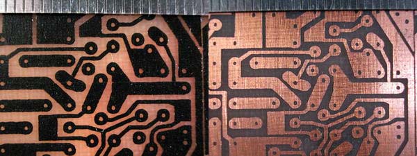
The photo shows for comparison two printed circuit boards made with the help of LUT and permanent marker.
activate a few drops of solvent (you can remove a varnish fluid) on a freeze and remove the toner residues from the board, you must only have copper tracks. Act carefully, then dry the fee with a clean cloth. Cut the fee to the desired size and process the edges of the sandpaper.
Drill mounting holes and solder all components on the fee.
Step 13: Conclusion
- Laser-ironing technology is a completely efficient way to manufacture printed circuit boards at home. If you do everything neatly, each track will be clear.
- Performing a wiring with a permanent marker is limited to our artistic skills. This method is suitable for the simplest schemes, for something more complex it is better to produce a fee in the first way.
Homemade printed fee
How to make a printed circuit board with a laser-iron technology. This refers to the thermal transfer of toner from paper to the surface of the metallization of the future printed circuit board.
Many times tried to make a printed circuit board using laser-iron technology, but I never managed to get a reliable easily repetitive result. In addition, in the manufacture of the board, I need divergent holes in the contact venues of no more than 0.5 mm. Subsequently, I use them when drilling, in order to poison the drill with a diameter of 0.75mm.
Marriage manifests itself in the form of displacement or change of the width of the tracks, as well as in the unequal thickness of the toner remaining on the copper foil after removing the paper. In addition, when removing paper before etching, it is problematic to clean each hole in toner from cellulose residues. As a result, there are additional difficulties in etching a printed circuit board, which managed to avoid only by doing the other way around. http://oldoffober.com/ru/
I assume that the reason that causes the next marriage.
Paper, heating to high temperatures begins to breed. While the temperature of the foil glass is always slightly lower. The toner is partially fixed on the foil, but remains molten from the paper side. When charging, the paper shifts and changes the initial shape of the conductors.
At the very beginning I want to warn that the technology is not deprived of certain flaws.
The first, this is the lack of special paper for thermal transfer, instead of which I propose to choose the appropriate paper for self-adhesive labels. Unfortunately, not every paper is suitable. You need to choose the one in which the labels are denser, and the substrate has a good, smooth surface.
The second drawback is that the size of the printed circuit board is limited to the size of the ion sole. In addition, not every iron can hardly heat the foil fiberglass, so it's better to choose the most massive one.
However, with all these shortcomings, the technology described below allowed me to obtain a stable, easily repetitive result, with small-sector production.
The essence of the change in the traditional process is that it is proposed to heat not paper with a toner, but the foil fiberglass itself.
The main advantage is that in this method it is easy to control the temperature in the melting area of \u200b\u200bthe toner. In addition, the rubber roller allows you to evenly distribute the pressure and prevent the toner crushing. (I am writing about the folgized glassstolite everywhere, since other materials have not experienced).
The technology is equally well suited for a foil glass fiberstolite of different thicknesses, but it is better to use the material not the thickness of one millimeter, as it is easy to cut with scissors.
So, we take a piece, the most that neither there is a shabby foil glassstolite and process it with a skin. It is not worth using a very large skirt, as you can damage the future tracks. However, you can not hide if you have a piece of new fiberglass. The surface of the copper is required to clean and degrease in any case.

We make stencil for thermal transfer. For which you cut off the desired piece from the sheet of paper for labels, we separate the label from the substrate. At the beginning of the sheet, you need to leave a piece of labels to prevent the substrate jam in the printer mechanism.
It should not be touched by the hands of those places on the substrate, where the toner will be applied.

If the thickness of the foil glass is one and less than a millimeter, then the distance between the edges of the individual circuit boards can be chosen 0.2mm, if more and you are going to cut the workpiece with a hacksaw, then - 1.5-2.0mm, depending on the thickness of the web and tolerance for processing.

Layer Toner I use the one that is laid by default in the printer draver, but "B & W Halftones:" (b / b halftone) should choose "Solid" (solid). In other words, you need to prevent the appearance of a raster. You can not see it on the stencil, but it can affect the thickness of the toner.

Fix the stencil on the segment of foil fiberclass by stationery clips. Another clips cling to the free edge of the stencil so that he does not get in touch with the iron.
The melting point of the toner of different grades is approximately 160-180s. Therefore, the iron temperature should be slightly higher than 10-20s. If your iron is not heated to a temperature of 180c, it will have to regulate it.

Before heating, the sole of the iron should be carefully cleaned from fat and other contaminants!
We warm up the iron to a temperature of 180-190 degrees and tightly press to foil fiberglass as shown in the figure. If you position the iron differently, the board can warm up too unevenly, since the iron is usually heated at 20-30s stronger in a wide part. Without two minutes.

After that, we remove the iron and one movement, with an effort to press the stencil to the foil fiberglass using a rubber roller for rolling photos.
If the toner is crushed during the pressing, that is, the tracks are in the direction or change their outlines, then the amount of toner in the printer driver should be reduced.
It is necessary that the center of the roller always moved along the board center. The roller handle must be kept so as to prevent the appearance of the vector of the direction of the directional "around" the handle.

A few more times we ride the stencil and press the resulting "sandwich" with something heavy, having previously folded the newspaper several times in order to evenly distribute the weight.
Turn the stencil follows every time in the same side. The roller begins to move from the place of attachment of the stencil.

For about ten minutes, you can remove the press and remove the stencil. That's what happened.


Now you need to glue something to the reverse side of the board, for which it will later be possible to hold this fee when etching. (I use thermoclauses.)

Pool fee in chlorine iron solution.
How to make a solution?
If the bank with chlorine iron is unloaded, then there, most likely, there is already a supercontrified solution. It can be merged into the dishes for etching and add some water.
If the chlorine iron has not yet been covered with water, then this can be done. Probably, you can get the crystals themselves from the can, but do not use the family silver for this.
Keep in mind, in the weaponcentric solution, the etching process will not go, therefore, having received such a solution, you need to add some water.
As a dishes, it is best to use the photo of a vaniplast bath, but you can and any other.
The picture shows that the board floats on the surface of the solution due to its surface tension. This method is good because the etching products are not delayed on the surface of the board, and immediately fall on the bottom of the bath.

At the very beginning of etching, you need to make sure that there are no air bubbles under the board. In the process of etching it is desirable to check that etching takes place evenly on the entire surface of the board.
If there is some kind of inhomogeneity, then you need to activate the process of an old toothbrush or something like that. But it is necessary to do it carefully not to destroy the layer of toner.
Special attention should be paid to holes in the contact sites. Places where the etching process did not go immediately - brighter. In principle, it is enough at the very beginning of the process to achieve darkening of the entire surface and all holes and then success is predetermined.

If the main part of the board was caught in 15 minutes, then it is not worth increasing the total etching time more than twice, that is, more than 30 minutes. Further etching will not only reduce the width of the conductors, but can also partially destroy the toner.
Usually, all the holes of 0.5mm in the contact sites are etched for doubled time.
The motor twists a small eccentric, which creates vibrations in the solution (not necessarily, if it periodically lifts and move the fee).
We wash off toner tampon moistened in acetone.
That's what happened. On the left, the board is still covered with toner. Width of the tracks 0.4mm.

Now you can remove burrs formed on copper when drilling. For this, we first ride them with the help of a ball bearing attached to some comfortable mandrel. At the same time, the fee is better to place on a solid flat surface. Then, we remove the shallow skin from the surface of the copper, if it was formed.

Ludith the workpiece, for which it is pre-coated its flux layer.


I went to the stationery store and photographed the packaging with self-adhesive labels. This paper is poorly suitable for thermal transfer. Although, if there is no different, then you can use this after some refinement.

Paper, which turned out to be the most convenient for thermal transfer, was the production of the Finnish company "Campas". And since there are no identification signs on fine packaging, it is hardly possible to identify it without testing.