Submersible pump with hydroaccumulator and pressure relay. How to install a water supply system for water supply
The hydroaccumulator is a special metal hermetic containing inside an elastic membrane and a certain amount of water under certain pressure.
The hydroaccumulator (in other words - the membrane tank, hydrobacom) is used to support stable pressure in the water supply, protects the water pump from premature wear due to frequent inclusion, protects the water supply system from possible hydrowards. When the voltage is disconnected, thanks to the hydroaccumulator, you will always be with a slight water margin.

Here are the main functions that perform a hydroaccumulator in the water supply system:
- Pump protection from premature wear. Due to the water supply in the membrane tank, when opening a water tap, the pump will be turned on only if the water supply in the tank runs out. Any pump has a specific inclusion rate per hour, therefore, thanks to the hydroaccumulator, the pump has a stock of unused inclusions, which will increase its life.
- Support for constant pressure in the plumbing system, protection against water pressure drops. Due to the pressure drops, with simultaneous inclusion of several cranes, sharp fluctuations in the water temperature occur, for example, in the shower and in the kitchen. The hydroaccumulator successfully copes with such unpleasant situations.
- Preservation of hydrotarians that may occur when the pump is turned on, and are capable of swaying the pipeline.
- Maintaining the stock of water in the system, which allows water to use even during the disconnection of electricity, which is quite common in our time. This feature is especially valuable in country houses.
Device hydroaccumulator

The hermetic case of this device is divided into a special membrane into two chambers, one of which is intended for water, and the other for air.
Water does not come into contact with metal surfaces case, since it is located in a water chamber-membrane made of a strong rubber material of butyl, resistant to the effects of bacteria corresponding to all hygienic and sanitary standardsplaced on drinking water.
The air chamber is a pneumatic valve, the purpose of which is to regulate the pressure. Water enters the hydroaccumulator through a special connecting nozzle on the thread.
The hydroaccumulator device must be mounted in such a way that it can be easily dismissed in the case of repair or prevention, without merging all the water from the system.
The diameters of the connecting pipe and the pressure pipe must, if possible, coincide with each other, then this will avoid unwanted hydraulic losses in the system pipeline.
In the membranes of hydroaccumulators, more than 100 liters are a special valve for watering the air highlighted from water. For small hydroaccumulators in which there is no such valve, in the water pipe system, an air bleeding device must be provided, for example, a tee or a crane that overlaps the main line of water supply system.
In the aircraft accumulator aircraft, the pressure must be 1.5-2 atm.
Principle of operation of the hydroaccumulator
The hydroaccumulator works like this. The pump serves water under pressure in the hydroaccumulator membrane. When the pressure threshold is achieved, the relay turns off the pump and the water stops feeding. After when the water fence, the pressure begins to fall, the pump again automatically turns on and supplies water into the hydroaccumulator membrane. The greater the amount of hydrobook, the more efficient the result of its work. Pressure relay operation can be adjusted.
During the operation of the hydroaccumulator, the air dissolved in water gradually accumulates in the membrane, which leads to a decrease in the efficiency of the device. Therefore, it is necessary to make the prevention of the hydroaccumulator, whipping the accumulated air. The frequency of prophylaxis depends on the volume of hydrobacock and the frequency of its operation, which is approximately once in 1-3 months.

These devices can be vertical and horizontal configuration.
The principle of operation of devices does not have differences, except that the vertical hydroaccumulators with a volume of more than 50 liters in the upper part have a special valve for airbagging, which gradually accumulates in the water supply system during operation. The air accumulates in the upper part of the device, because the location of the valve is selected in the upper part.
In horizontal devices for air booming, a special crane or drain is mounted, which is installed behind the hydroaccumulator.
From the devices of small sizes, regardless of whether they are vertical or horizontal, the air is poured with a complete drain of water.
Choosing the shape of the hydraulicock, proceed from the size of the technical room, where they will be installed. It all depends on the dimensions of the device: which is better fit into the place allotted for it, it will be installed, regardless of whether it is horizontal or vertical.
Connection diagram hydroaccumulator
Depending on the assigned functions, the circuit of the connection of the hydroaccumulator to the plumbing system can be different. The most popular hydroaccumulators connection schemes are shown below.

Such pumping stations are installed where large water consumption is present. As a rule, one of the pumps at such stations is constantly working.
On rising pumping station The hydroaccumulator is used to reduce pressure jumps during the inclusion of additional pumps and for compensation for small waters.
Even such a scheme is widely used when a frequent interruption of electricity supply is obtained in the water supply system, and the presence of water is vital. Then the water supply in the hydroaccumulator saves the position, playing the role of a backup source for this period.
The larger and more powerful pumping station, and the greater pressure it should support, the greater the volume of the hydro-accumulator acting the role of the damper.
Buffer capacity The hydraulicock also depends on the volume of the required stock of water, and on the difference in pressure when the pump is turned on and disconnected.

For long-lasting I. uninterrupted work The submersible pump must be made from 5 to 20 inclusions per hour, which is indicated in its technical specifications.
When the pressure drops in the plumbing system minimum meaning Automatically turns on the pressure relay, and at the maximum value, it turns off. Even the most minimal water consumption, especially in small water supply systems, can reduce pressure to a minimum, which will instantly give the command to turn on the pump, because water leakage is compensated by the pump instantly, and after a few seconds, when the water supply is replenished, the relay will turn off the pump. Thus, with minimal water consumption, the pump will work almost frightened. Such a mode of operation adversely affects the operation of the pump and can quickly bring it out of order. The position can fix the hydroaccumulator, which always has the desired supply of water and successfully compensates for its slight consumption, and will also protect the pump from frequent inclusion.
In addition, the hydroaccumulator connected to the diagram smoothes a sharp increase in pressure in the system when the submersible pump is turned on.
The volume of the hydraulicock is selected depending on the frequency of inclusions and power of the pump, water consumption per hour and the height of its installation.

For cumulative water heater In the connection scheme, the hydroaccumulator plays the role of expansion tank. Heating, water expands, increasing the volume in the water supply system, and since it does not have the properties to shrink, the minimum increase in the volume in the closed space increases the pressure and can lead to the destruction of the elements of the water heater. Here, too, will come to the aid of the Hydrobac. Its volume will directly depend on and increase from increasing the volume of water in the water heater, increase the temperature of heated water and growth maximum permissible pressure In the water supply system.

The hydroaccumulator is connected to the rising pump along the water. It is needed to protect against a sharp decline in pressure in the water supply network at the moment of inclusion of the pump.
The capacity of the hydroaccumulator for the pumping station will be the greater the greater the water in the water supply system and the smaller the difference between the upper and lower pressure scale in the plotting in front of the pump.
How to install a hydroaccumulator?
Of all the above, it can be understood that the device of the hydroaccumulator absolutely does not look like an ordinary water tank. This device is constantly in operation, the membrane is all the time in the dynamics. Therefore, the installation of the hydroaccumulator is not so simple. The tank must be strengthened when installing securely, with a margin of strength, noise and vibration. Therefore, the tank is fixed to the floor through rubber gaskets, and to the pipeline through rubber flexible adapters. It is necessary to know that at the inlet of the hydraulic system, the submarine cross section should not be narrowed. And another one important detail: The first time the filling tank is needed very carefully and slowly, using a weak water pressure, in case the rubber pear merged from long inactivity, and with a sharp pressure of the water it may be damaged. Best of all before commissioning, remove all air from a pear.
Installation of the hydroaccumulator should be carried out so that during operation to it it was possible to fit freely. It is better to entrust this task to experienced specialists, since very often the tank fails because of some unaccounted, but important little things, for example, due to the inconsistency of the diameter of pipes, non-regulated pressure, etc. Here it is impossible to conduct experiments, because there is a normal operation of the plumbing system.

Here you brought the house purchased hydrobac. What to do with him next? Immediately need to find out the pressure level inside the tank. Typically, the manufacturer pumped it on 1.5 atm, but there are such cases when due to leakage, the sales time indicators are reduced. To make sure in the correctness of the indicator, it is necessary to unscrew the decorative cap on the ordinary automotive spool and check the pressure.

What to check it? Typically, this is used to make a pressure gauge. It can be electronic, mechanical car (with a metal case) and plastic, which is supplied complete with some pump models. It is important that the pressure gauge is greater accuracy, since even 0.5 atm changes the quality of the hydraulic work, so plastic pressure gauges are better not to use, as they give a very greater error in the indicators. This is usually Chinese models in a weak plastic case. The indicators of electronic pressure gauges affect the charge of the battery and the temperature, besides, they are very expensive. therefore optimal option is an ordinary car pressure gauge, past check. The scale must be on a small amount of divisions, for the possibility of more accurate pressure measurement. If the scale is designed for 20 atm, and you need to measure only 1-2 atm, then you do not have to expect high accuracy.

If there is less air in the tank, it means there is a greater supply of water, but the difference in pressure between the empty and almost filled tank will be very significant. It's all in preferences. If it is necessary that the water supply is constantly high under the water, then the tank should be a pressure of at least 1.5 atm. And for household needs, it may well be enough and 1 atm.
At a pressure of 1.5 ATM, the hydrobacom has a smaller supply of water, which is why the rolling pump will be turned on more often, and in the absence of light of water in the tank, it may simply be enough. In the second case, it will have to sacrifice pressure, because you can take a shower with a massage when the tank is filled, and as it devms it - only the bath.
When you decide that it is more important for you, you can install the desired mode of operation, that is, either pump air into the tank, or to put extra.
It is undesirable to reduce the pressure less than the mark of 1 atm, as well as overly exceed. Pear-filled pear with insufficient pressure will touch the walls of the tank, and can quickly come into disrepair. And excessive pressure will not allow you to download the sufficient volume of water, as most of the tank will be occupied by air.
Setting up pressure relay
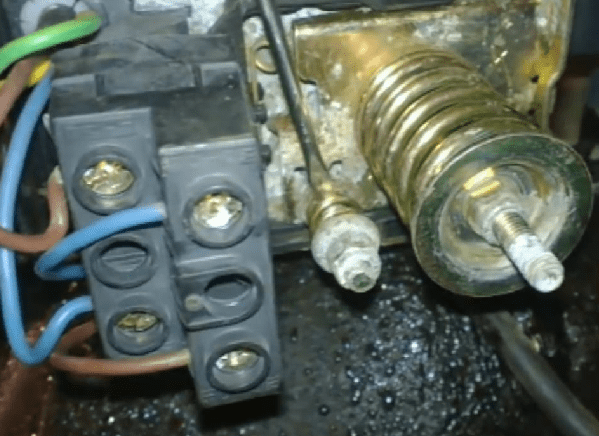
You also need to configure the pressure relay. Opening the cover, you will see two nuts and two springs: large (p) and small (delta R). With their help, you can configure the maximum and minimum levels of pressure at which the pump is turned on and off. For the inclusion of the pump and the pressure corresponds to the large spring. By design, you can see that it contributes to the water to close the contacts.

With the help of a small spring, the pressure difference is set, as stipulated in all instructions. But the instructions do not indicate the reference point. It turns out that the point of reference is the Nut of the spring r, that is, the lower limit. The lower spring, which is responsible for the pressure difference, resisting the pressure of the water, moves the movable plate from the contacts.

When the correct air pressure is already set, you can connect the hydroaccumulator to the system. By connecting it, you need to carefully monitor the manometer. All hydroaccumulators indicate the values \u200b\u200bof normal and extreme pressures, the excess of which is unacceptable. Manual disconnection of the pump from the network occurs when the normal pressure of the hydroaccumulator is reached, when the boundary value of the pump pressure is reached. This happens when the pressure increases stops.
The pump power is usually not enough to pump up the tank to the limit, but, even there is no particular need, because when pumping, the life and pump and pears are reduced. Most often, the pressure limit for shutdown is set to 1-2 atm higher than inclusions.
For example, when reading a 3 ATM pressure gauge, which is enough for the needs of the pumping station owner, you need to turn off the pump and slowly rotate the small springs nut (delta P) to decrease, before the mechanism is triggered. After that, you need to open a crane and drain the water from the system. Watching the manometer, it should be noted that the value in which the relay will turn on is the lower pressure limit when the pump is turned on. This indicator should be slightly larger than the pressure indicator in the empty hydroaccumulator (0.1-0.3 atm). It will give the opportunity to serve a larger period of time.
When the nut rotates the large spring P, the lower limit is set. To do this, turn on the pump to the network and wait until the pressure reaches the desired level. After that, you need to adjust the nut with a small spring "Delta P" and finish the setting of the hydroaccumulator.

In the aircraft accumulator air chamber, the pressure must be 10% lower than the pressure when the pump is turned on.
The exact air pressure indicator can be measured only when the tank is disconnected from the water supply system, in the absence of water pressure. Air pressure must be kept constant under control, if necessary, regulate, which will add membrane life. Also, to continue the normal operation of the membrane, it is impossible to allow a large pressure drop when the pump is turned on and off. Normal is the difference in 1.0-1.5 atm. The stronger pressure drops reduce the service life of the membrane, strongly stretching it, besides, such pressure drops do not give the possibility of comfortable use of water.
Hydroaccumulators can be installed in places with low humidity, surrendered flooding so that the device flange is successfully served for many years.
Choosing a brand of the hydroaccumulator, it is necessary to pay special attention to the quality of the material from which the membrane is made, check certificates and sanitary and hygienic conclusions, making sure that the hydraulician is designed for systems with drinking water. You also need to make sure that there are spare flanges and membranes that should be included so that in the event that the problem has not had to buy a new hydrobacom.
The limit pressure of the hydroaccumulator, which it is designed must be no less than the maximum pressure in the water supply system. Therefore, most devices maintain a pressure of 10 atm.

To determine which stock of water can be used from the hydroaccumulator when the electricity is turned off when the pump stops swinging water from the water supply system, you can use the table of fill in the membrane tank. The water supply will depend on the pressure relay setting. The higher the pressure difference when the pump is turned on and off, the greater the water supply will be in the hydroaccumulator. But this difference is limited by the above reasons. Consider the table.

Here we see that in the membrane tank of 200 liters when settings for pressure switch, when the pump is turned on 1.5 bar, turning off the pump - 3.0 bar, air pressure is 1.3 bar, the water supply will be only 69 l, which is approximately a third of the total tank .
Calculation of the required volume of the hydroaccumulator
To calculate the hydroaccumulator, use the following formula:
Vt \u003d k * a max * ((PMAX + 1) * (PMIN +1)) / (PMAX- PMIN) * (PUPP. + 1),
- AMAX is the maximum consumption of liters of water per minute;
- K is a coefficient that depends on the power of the pump engine;
- PMAX - pressure when the pump is turned off, bar;
- PMIN - pressure when the pump is turned on, bar;
- Podvad. - Air pressure in the hydroaccumulator, bar.
As an example, we will select the required minimum volume of the hydroaccumulator for the water supply system, taking, for example, the Aquarius pump of the BCPE 0.5-40 y with such parameters:
| PMAX (bar) | PMIN (bar) | Podes (bar) | A MAX (cubic / h) | K (coefficient) |
| 3.0 | 1.8 | 1.6 | 2.1 | 0.25 |
Using the formula, calculate the minimum amount of ha, which is 31.41 liters.
Therefore, we choose the next nearest size of hectares, which is 35 liters.
The volume of the tank in the range of 25-50 liters is ideally consistent with all methods for calculating the volume of hectares for household water supply systems, as well as with empirical appointments. different manufacturers pumping equipment.
With frequent shutdown of electricity, it is advisable to choose a tank of the larger volume, but at the same time it should be remembered that water will be able to fill the tank only by 1/3 of the total. The more powerful the pump in the system is installed, the greater should be the volume of the hydroaccumulator. This size correspondence will reduce the number of short inclusions of the pump and will extend the life of its electric motor.
If you bought a large-volume hydroaccumulator, you need to know that if it does not use water regularly, it is stood in the tank hectare and its quality deteriorates. Therefore, choosing in the store a hydraulician, you need to take into account the maximum amount of water used in the water pipe system at home. After all, with a small flow rate of water, it is much more expedient to use a 25-50 liter tank than 100-200 liters., Water in which will disappear in vain.
Repair and prevention of the hydroaccumulator
Even the simplest hydraulicocks require attention and care, like any working and benefit device.
Rates for the repair of the hydroaccumulator are different. These are corrosion, dents of the case, disruption of the integrity of the membrane or disruption of tank tightness. There are also many other reasons that bind the owner to repair the hydraulician. To prevent serious breakdowns, it is necessary to regularly examine the surface of the hydroaccumulator, monitor its operation to prevent possible problems. It is not enough to inspect heaven twice a year, as stipulated in the instructions. After all, it is possible to eliminate one fault today, and tomorrow you do not pay attention to another problem that has become irreparable for half a year and can lead to the exit of the hydrobacing. Therefore, the hydroaccumulator needs to be inspected at every opportunity, so as not to miss the slightest faults, and in time to repair their repair.
Causes of breakdowns and their elimination

The cause of the breakage of the expansion tank may be too frequent on-shutting down the pump, the water output through the valve, weak water pressure, weak pressure air (below the calculated), weak water pressure after the pump.
How to eliminate the malfunction of the hydroaccumulator with your own hands? The reason for the repair of the hydroaccumulator can become a weak air pressure or its absence in a membrane tank, damage to the membrane, damage to the case, a big difference in the pressure when the pump is turned on and off, incorrectly selected hydraulic volume.
Eliminate malfunctions as follows:
- to increase the air pressure, it is necessary to make it discharge through the nipple of the tank with a garage pump or compressor;
- the damaged membrane can be restored in the service center;
- the damaged housing and its tightness is also eliminated in the service center;
- it is possible to correct the difference in pressures by exposing too much differential in accordance with the frequency of pump inclusions;
- the adequacy of the volume of the tank must be defined before it is installed in the system.
Any water supply system, even assembled perfectly and from quality equipmentmay experience malfunctions in work.
The most common problem is to reduce the pressure in the system, which is why water can not get to the water treatment point.
To solve this problem, the device, accumulating water and containing compressed air.
It is at the expense of the latter that it works: the water is recruited into the battery pump, after which it is pushed into the system due to air pressure. This allows water pressure in the water supply system is always on the same level.
So that everything worked without malfunctions, you need to connect the unit to the source of the water - well, the well or water supply. You can make it with your own hands in several ways.
Mounting with a submersible pump
Connection diagram of the hydroaccumulator to the downhole pump. (To enlarge, press) if the water in the water supply system is taken from the well, the pump that swings water into the hydroaccumulator is located underground.
The main feature of this connection scheme is the presence in the check valve system.
Thanks to this adaptation, pumped water will not be able to lean back to the well.
Installation of the check valve is carried out before connecting the remaining elements of the system. It is installed directly on the pump in one end, the pipeline that goes to the hydroaccumulator is connected to the other.
happens in the following order:
- The depth is measured on which the pump is to be omitted so that it does not take to the bottom of the well or well by about 30 cm. For measurement, a rope is used with a cargo.
- The pump with the connected valve is lowered into the well and is fixed by the insuruction cable.
- Pipe from the pump that goes on the surface is connected to through the nozzle.
- In addition, the stacker is connected by a hydroaccumulator, consumption water supply and control system. Thus, you will need a five-disconnected fitting.
Take into account: It is very important to do all the connections to hermetic, for which you can use the FMUn tape or a conventional pass, impregnated with sealant.
Installation with surface pump
If water into the system is pumped from the water supply system and the pump immersion is not required, it can be installed next to the battery itself.
In its essence, the connection scheme does not change, but there are some nuances that are important to know.
Before connecting, you must calculate working and minimum pressure. For different systems, a different water pressure indicator may be required, but standard for small systems Water supply with a small number of water intake points is a pressure of 1.5 atm.
If the system has equipment that requires high pressure, this indicator can be increased to 6 atm, but no more, since higher pressure will be dangerous for pipes and their connecting elements.
Determination of critical pressure
Based on the working value, it is determined by how minimal pressure should be, that is, such an indicator at which the pump will start.
This value is installed using a relay, after which the pressure in the empty hydroaccumulator should be measured.
The result should be below the critical value by 0.5 - 1 atm. After that, the system is going.
Its center, as in the previous case, will be a five-disconnecting fitting, which is connected to each other:
- hydroaccumulator itself;
- pipe from the pump connected to the water source;
- household water supply;
- relay;
- manometer.
Pressure relay connection
 In order for the relay to work correctly, it is necessary not only to connect to the fittings correctly, but also customize.
Electricity needs to be operating.
The top cover is removed from the device, under which contacts are connected to connect the relay to the network and to the pump.
Usually contacts are signed, but may not have designations. If you are not sure where it connects, it is better to turn to a professional electrician.
Pumping station
 The pumping station is a complex of equipment that includes powerful patching equipment, a hydroaccumulator and controlling devices.
As a result, the connection scheme in this case does not differ from the connection to the usual pump.
If the station is calculated for large volumes of water - for example, in the case of eating several houses from one well - the connection is somewhat complicated.
In this case, several pumps are used and two fittings - the patching system is connected to one, and the second is the first fitting and the rest of the equipment.
The hydroaccumulator can be connected not only to the well or water supply for the water supply system, but also to the heating system. The functions of the unit will in this case will be somewhat different, although the principle of operation does not change.
See the video in which a specialist explains in detail how to connect the hydroaccumulator to the water supply system with your own hands:
The main elements of the autonomous pumping station - the pump, the accumulative capacity, pressure switch for the hydroaccumulator and. Pressing unit pumps the specified volume of water into the network. The hydroaccumulator accumulates and maintains constant pressure for water supply to the consumer. The control assembly provides a stable cycle of the cooling water supply system. Consider more, where it is used and how to configure the hydroaccumulator and pressure switch.
The relay adjusts the on and off of the device feeding water into the hydraulic
Hydroaccumulator in the cold water supply system
Direct submersible connection or surface pump It is the cause of unstable water supply. The pressure unit operates in the minimum water consumption. The presence of a gravitational or pneumatic drive in the system does not require constant operation of the primary pressure supercharger. Backup container supports permanent flow Water for economic drinking needs. The supply of water reduces the dependence of individual water supply from external factors.
The gravitational design of the hydroaccumulator is an atmospheric tank with a float level sensor. The open tank is installed on the attic of the house, above the water take-off points. The pressure in the system creates a fluid column weight. The pump runs the float mechanism or level sensors.

Photo: Pumping station with hydroaccumulator
Modern hydraulic drives for autonomous water supply are operated due to excess pressure in the air chamber. The principle of operation of pneumatic batteries is built on the interaction of compressed air and water. The pump pumped water into a rubber pear, which is inside the hull. The size of the air chamber decreases, and the pressure increases. In the intervals between the inclusions of the unit, the air pushes the supply of water from the membrane into the network of the consumer.
Water does not come into contact with the inner walls of the hermetic cylinder. The air chamber separates the membrane from the metal case. If the hydroaccumulator is used in the drinking water supply system, the membrane material is chemically neutral rubber. When using a battery tank in a heating system or hot water supply, membranes with high resistance to high temperatures are used.

There are vertical and horizontal models of pneumatic accumulating tanks of various capacities. Connection diagram of the hydroaccumulator determines the type of pump and the storage model. Horizontal tanks are used for remote surface units. Pressure supercharger is installed on the platform, in the upper part of the drive housing (i.e., the cylinder is below the self-priming pump).
Pumping stations with submersible units are equipped with vertical drives. The hydroaccumulator is above the level of installation of the depth pump.
The volume of the hydropneumatic tank-drive depends on the time consumption of water, power and the inclusion frequency of the pump, the height of the pipeline system. The greater the water consumption and the less pressure drop on / off the pump, the larger the capacity of the hydroaccumulator.

Photo: typical scheme Autonomous Water Supplies from the Well
Design elements of the hydroaccumulator:
- hermetic metal case designed to work under pressure (1.5 ÷ 6 atmospheres);
- elastic membrane - inner capacity for water supply;
- flange with valve for fastening the membrane to the body and filling it with water;
- nipple for air pump in the balloon air chamber;
- valve for resetting air from the water chamber (for hydroaccumulators, the volume of which exceeds 100 liters);
- bracket for mounting a small capacity on the wall or support legs, with installation rubber gaskets for more capacity models;
- the horizontal tank kit includes a support bracket for co-setting the surface pump with a hydroaccumulator and pressure relay.
Important! Primary filling of the hydraulic battery cylinder with water produced gradually so as not to damage the integrity of the pear, because After storing the wall, the rubber membrane usually glued.

Pumping station will help achieve a full autonomous water supply of cottages
Calculation of the volume of hydroaccumulator
The method of selection of the hydroaccumulator is designed for individual houses that consume a large amount of water (sewage, bathroom, shower, several faucets, bidet, washing and dishwasher). By the number of waterproof points, the total consumption ratio and the maximum water consumption for economic and drinking needs are determined. The volume of the hydroaccumulator is determined by the formula:
V is the volume of the hydroaccumulator, l;
Qamax is the maximum water consumption for economic and drinking needs, l / min;
a - the number of system starts per hour (recommended value of 10 starts);
Rmin - Pressure Pump, ATM.;
RMAKS - pressure of the pump, atm.;
PO - pressure of the air chamber of the hydroaccumulator, atm.

Water construction consists of: 1 - hydroaccumulator; 2 - pump; 3 - pressure relay; 4 check valve; 5 - Power Supplies
Standard water supply installation for small house Seasonal accommodation, as a rule, is equipped with a 24-liter hydroaccumulator. For the house with the number of disarm points, 50 liters are chosen. And B. technical passport Equipment The manufacturer indicates the total volume of the cylinder (an air chamber including).
Adjusting the operating pressure of the hydroaccumulator
For domestic water supply one-storey houses, The pressure value in one atmosphere is considered sufficient. However, it should be borne in mind that the air pressure of the air chamber should exceed the magnitude of the static pressure of the highest point of water take-off.
The maximum pressure of the shutdown depends on the pressure chart. The pressure that pumps the pump divided by 10 corresponds to the value of the upper threshold for the automatic water supply system. The amendment is made on linear hydraulic resistance, real voltage electrical network, technical condition of the equipment and the height of the water supply system at home.

Accessories for water pressure adjustment in hydraulic
The recommended difference between the pressure on and off pressure for autonomous water supply is 1.0 ÷ 1.5 atmosphere. An increase in the factory setting (1.5 atmosphere) will reduce the backup volume and increase the pressure in the system. High pressure Cold water supply increases consumption, leads to irrational use of energy resources.
The formula for calculating the value of the desired pressure in the hydroaccumulator:
H Max is height in meters from the central line of the hydroaccumulator to the upper point of the water selection (for a two-story private house 6 ÷ 7 meters).
Air pressure in the air chamber of the damper capacitance is checked and adjustable before installation, with settings failure or impaired water supply mode. During adjustment, the power of the pumping station is disconnected from the network, water from the hydroaccumulator is drained.

All elements are bonded with each other with fittings
Air chamber pneumatic valve is located under a decorative cap on the body of the tank. The correspondence or deviation of the pressure from the specified operating parameters is determined using a pressure gauge connected to the spool. According to the measurement results, the excess air is blending or pump the air chamber pressure by the automotive pump.
If the operating parameters of the hydroaccumulator do not bring the desired result, then the pressure relay settings are checking.
Relay device for hydroaccumulator
The relay manages the operation of the pump and adjusts the filling of the pneumohydraulic drive. The device combines, controls and regulates the operation of the cold water supply system.
The appearance of the pump management site is reminiscent of a small plastic box. The device is mounted at the entrance to the tank drive. Pressure relay for the hydroaccumulator consists of a mechanical and electrical part.

Relay for the hydroaccumulator in disassembled form
Standard design elements:
- plastic housing (cover with screws and base);
- metal membrane cover (with a nut for joining the pipeline);
- rubber membrane;
- brass piston;
- two studs with carvings and nuts;
- large and small adjusting springs;
- metal plate base;
- hinged platform;
- electric contact assembly with a flat spring;
- cable clutches;
- terminal block.

Design and adjustment
Spring Adjustment Mechanism and Connection Box Protects Plastic Cover. Metal base plate from below supports a plastic case. The base separates the working body (piston membrane) from the actuator (hinged platform, two adjusting springs on the heels and an electric pin knot).
The electrical part of the relay represents a two-contact switching relay of electrical circuits. The legs of the electrical contact node are clamped between the metal plate of the base and the plastic case. Two couplings for the cable clamp (from the network and the pump power line) and the relay connections node to the hydroaccumulator are located on the base of the plastic case.
Standard diameter of the supply nozzle ¼ inches. On the side of the device, the internal cross section of the mounting nut to the adapter is limited to the rubber membrane. The reciprocating movement of the elastic membrane is reported to a brass piston, which transmits the effort to the hinge metal platform.

Pressure gauge is used to measure water pressure
From above, on the movable edge of the platform, the large and small spring, which counteract the force of the piston. A large spring compression ratio adjusts the pump to turn on. The deformation range of a small spring provides a disconnection of the pressure unit.
Methods for connecting the relay to the hydroaccumulator
There are a pressure switch connections to the water and electricity water and electricity.
How to connect pressure relays on water?
Connecting nozzle connection of the pressure switch of the hydroaccumulator to the pipeline is rigidly fixed. The device is mounted in the assembled state. Before starting assembly, you need to provide sufficient space to rotate the housing when installing the pressure relay.
The device is screwed into a separate thread embedded in the pipeline or make an installation directly on the outlet nozzle of the hydroaccumulator through a special fitting. Five outlet fitting allows you to install a control pressure gauge next to the control device of the pump work.

Connecting wires to the hydroaccumulator relay
How to connect the relay to the hydroaccumulator by electrical part?
Direct switching on the pressure relay is produced from the network 220V, provided that the power of the pump's operating current does not exceed 10 amps.
Before connecting the cable from the device, a protective plastic cover is removed. The electrical cable of the power supply or pump is set in the appropriate coupling. Outside, the wire is fixed with a nut with a crimp plastic ring. The designation of contact groups is indicated on the housing. The end of the cable is separated on the veins. Phase, neutral, grounding is cleaned with an insulating braid and connect to the terminals of the contact group.
Important!Electrical and adjusting works are carried out with the equipment disconnected from the network. The connection of the electrical part is performed in compliance with the regulatory rules of technical operation and safety in electrical installations.

The relay automates the operation of the pumping station and turns off the water supply when the specified mark is reached
Rule Rules Relay Hydroaccumulator
The relay controls the minimum and maximum pressure in the battery tank, supports the pressure difference when the pump is turned on / disabled. The limit of permissible setting values \u200b\u200bof the relay depends on the time consumption and power of the pump.
Factory settings are indicated in the product data sheet. The standard pressure relay setting for water supply systems is 1.0 ÷ 5.0 atmospheres. Starting pressure - 1.5 atmosphere. Range of operation of the pump - 2.5 atmosphere. The maximum power outage pressure is 5.0 atmospheres.
If the factory settings are not relevant or a malfunction failed, the setting and adjustment of the water pressure relay is carried out on their own, using a pressure gauge. The measuring instrument is installed on a hydroaccumulator collector. The correction is made according to the testimony of the pressure gauge, after the pump turns off. The pressure drop is created by the discovery of the crane in the water selection point nearest to the hydroaccumulator.

Connecting the automatic unit to the submersible pump
The hydroaccumulator setting is carried out under pressure, without disconnecting the power supply station from the power supply. The pump must fill the cumulative capacity and lift pressure on the network. When the relay works and turn off the engine of the unit, it is necessary to remove the plastic cover cover and completely relax the degree of tension of the small spring mechanism.
How to adjust the relay to the minimum pump turning on?
Setting a large adjusting spring:
- the clamping nut is rotated clockwise to increase the starting pressure;
- weakening of the tension - reduces the pressure of the relay and turn on the engine;
- to verify the result of adjustment, the water tap is discovered and drained water until the pump is turned on.

Adjustment is carried out with two nuts: big and small
How to adjust the pump disconnection?
Small adjusting spring adjustment:
- small spring heel nut spin to increase the pressure difference;
- the weakening of the tension allows you to reduce the pressure of the engine shutdown;
- the correction result is checked by a test turning on the pump.
If the reading of the pressure gauge coincides with the desired value when the engine is turned on / off, the adjustment is completed. If it is impossible to adjust the current instrument on their own, use the services of qualified specialists or buy a new device. If it is decided to buy a pressure switch for a hydroaccumulator, then pay attention to the compatibility of working with pumping equipment and the method of connecting the device to power supply.

Automation with protection from dry running on the basis of four fittings
Important! Increasing the starting value of the factory setting of the pressure relay of the hydroaccumulator (above 1.5 atmospheres) creates a critical load on the hydroaccumulator membrane. The operating range of pumps is changed, taking into account the maximum allowable pressure for waterborne reinforcement. The limit pressure on which the sealing rings of mixers and cranes are calculated is 6 atmospheres.
Air-acuputor aircraft air pressure air pressure does not affect the operation of the pressure relay and the pumping station as a whole. The absence or lack of air leads to excessive stretching of the membrane and the response of the pump with each selection of water from the system. Increased overpressure of the air chamber reduces the volume of water supply in the membrane and the removal interval of the pressure setting. Frequent switching on-off pump reduces the timeline of the unit service.
The normal operation of the pumping station is possible, provided that the pressure of the hydroaccumulator air chamber is 10% below the pump turning on the pump. Competent adjustment and adjustment of the pressure switch and the hydroaccumulator will provide the operation of the pump without overload, the optimal filling of the drive with water. An integrated approach to setting up and adjusting the equipment will extend the service life of the membrane and will increase the reliability of the autonomous water supply system.
Video: Relay Overview, Pump Group Assembling for Connection
Stable, properly working water supply - the real merit of the host country house. Everyone who has been engaged in installing and maintaining autonomous System, knows how difficult it is to provide water failures dangerous to household appliances. One jump pressure - and a risk of breakdown arises dishwasher or gas water heater. To prevent possible problems, you need to refer to the specialists or connect the hydroaccumulator with your own hands.
Device and types of hydroaccumulators
Before connecting, it is necessary to get acquainted with its components and the appointment of each of them.
Hydroaccumulators of blue color Designed for water supply systems. Expansion tanks for heating systems have red

Scheme of the hydroaccumulator device: 1 - metal case, 2 - membrane, 3 - flange with valve, 4 - nipple for air injection, 5 - compressed air, 6 - legs, 7 - pump platform
The hydroaccumulator is called a metal tank, inside of which there is a rubber membrane in the form of a pear. Rubber (rubber) membrane is attached to the body with a flange with a nozzle.
The hydroaccumulator accumulates water under pressure. Pressure B. household apparatus (1.5 bar) is created using air, in production models - inert gas.
Compressed air can be downloaded inside the housing using a bicycle or car pump. When the water enters the inside of the tank, the compressed air prevents the pear break, having resisted. With its help, the pressure in the hydroaccumulator is adjustable. In the process of water, water from the machine moves into the system.
The hydroaccumulators are somewhat different in their intended purpose, so it can be divided into 3 types conditionally:
- For cold water. It applies and accumulates water, protects equipment from hydrowards with pressure jumps. Protects the pump from wear during frequent inclusions.
- For hot water. His difference is the ability to function in a high temperature environment.
- For heating systems ( expansion tanks). They are an important part of the heating systems of the closed type.
About the types of expansion tanks for heating systems, their advantages and minuses will learn from our following article :.
Place of hydroaccumulator in the water supply system
The pump pumps water from a well, well or water pipeline pipes into a hydroaccumulator, or rather, into the rubber membrane inside it. The process lasts until the pressure reaches a certain mark. Required pressure Exhibit on the relay controller, usually it is 1-3 atmosphere. Upon reaching the desired pressure indicator, the pump is disabled (automatically).
Suppose turned on washing machine, shower or faucet in the kitchen - water from the membrane immediately arrives back into the pipes. At the time when the pressure reaches the lower threshold, the relay works and turns on the pump again. Thus, the cycle begins again.
The video below will give a complete picture of how the hydroaccumulator works:
The inclusion frequency of the pump is directly dependent on the volume of the hydroaccumulator. The more his tank, the less the pump is turned on. Accordingly, the less often the pump is turned on, the longer they serve the flange with the valve, and the pump itself. Equipment put on the floor or mounted on the wall. In any case, its body from exploitation does not suffer.
Connection using the surface pump
Consider in stages, how to connect the hydroaccumulator to the water supply system if the surface type pump is used.
- Checking the air pressure inside the tank. It must be 0.2 - 1 bar less than the indicator marked on the relay (for the power on the pump).
- Preparation of equipment for connecting: Fitting on 5 outputs (serves to connect a hydroaccumulator, relay, pump and pressure gauge; another output, the fifth, is necessary for attaching the pipe of the water supply); pressure gauge; Pacle with sealant or tape FUM; Relay for pressure regulation.
- Attaching the fitting to the tank. The location of the connection can be either a hard hose, or a flange equipped with a bandwidth valve.
- Alternate screwing of the remaining elements: relay, pressure gauge, pipes leading to the pump.
Testing a system for leakage detection. Special attention is paid to compounds.

Connection diagram of the surface pump station is similar to the pump connection scheme
Connecting the pressure regulator relay, carefully study the tags. Under the lid are signed contacts: "Network" and "Pump". The main thing is not to confuse the wires. If there are no labels under the relay cover, a specialist (electrician) should be called to connect.
During the connection, you must follow sealing threaded connections. For a more dense fit, the pass (technical flax) is used with sealant or fume ribbon.
Connection diagram with submersible pump
The submersible type pump is characterized in that it is in a well or in a well, that is, right in that place, where the water is served in the house, in this case - in the hydroaccumulator.

Installation scheme of the hydroaccumulator in the water supply system with a well

Installation scheme of the hydroaccumulator with a submersible pump in the well
Here important role Playing check valvewhich insures the system from the receipt of water back to the well (well). The check valve is mounted in front of the pipe, directly to the pump. To do this, the inner thread is cut into its lid. Consequently, the fitting will have outdoor thread from all sides. First, the check valve is mounted, then the hydroaccumulator is connected to the water supply system.
An exemplary scheme for connecting the hydroaccumulator is as follows:

Having installed the fitting, it is necessary to check the tightness of the connections
To measure the length of the pipe leading from the submersible pump to the edge of the well (well), apply a rope with a cargo. Having lowered the cargo on the bottom, the top edge of the well is noted on the rope. Extend the rope, you can calculate the length from the bottom to the top point. We subtract the length of the pump and the distance from the location of the pipe to the ground to the top of the well. We also consider the location of the pump: it must be about 20-30 cm from the bottom.
What model of the hydroaccumulator to choose?
Manufacturers reacting to consumer requests, manufacture equipment different sizes. "Corridor" volume indicators - 24-1000 liters. What should be considered when choosing?

The volume of the tank depends on the amount of water consumed
The determining factor is the amount of water required for home maintenance (possibly and pricework). The minimum volume of the tank is 24 liters - enough for a family of 2 people, if you take into account the shower, toilet, kitchen and watering crops on the site.
More significant water consumption requires a tank of 50 liters. It should be calculated how many units of household appliances simultaneously use water, add the number of people, also using water, and, based on them, choose the desired model.
It happens that the number of users has increased or has a new household appliance using water. In this case, you should simply replace the container with a large tank in volume, since the connection of the hydroaccumulator is your own hands - the process is fast and simple.
One of the reasons why the pump is turned on more often and does not provide a smooth water supply, is incorrect adjustment of the pressure relay and setting the parameters of the hydroaccumulator. These are two different operations on different devices. And although the tank of the water accumulator does not have a relay or built-in automatic devicesThe pressure in the air pocket of the tank indirectly affects the work of the entire water supply system.
What and how to adjust in the system with a pump and a hydroaccumulator
To organize the normal operation of the pumping equipment, it is necessary to set three basic parameters:
- Adjust the air pressure in the airspace of the hydroaccumulator;
- Fix the level in which the control relay starts the water pump;
- The limiting pressure level of water at which the pump unit is turned off using the relay command.
Important! All three parameters will be required to adjust several times, adjusting a more comfortable pressure level in the water supply and water consumption on the hydroaccumulator under the characteristics for your home.
Adjust the pressure in the hydroaccumulator
The water accumulator device is very simple in design. Inside the steel tank there is a rubber membrane, occupying about 2/3 of the hydroaccumulator volume. The rest of the space takes the air chamber. With the help of overpressive air pressure in the chamber and the elastic forces of the tensile rubber membrane, water is extruded as needed to the water supply system. There is nothing particularly tune and regulate, except for the pressure in the air compartment of the hydroaccumulator.
From the factory, the device comes with pre-installed air pressure in 1.5 atm. Before buying a device, you should make sure that the factory pressure should be available. This usually indicates the health of the nipple and the integrity of the rubber shell inside the cylinder, we move to the adjustment of the hydroaccumulator for water supply systems.
First, the hydroaccumulator is installed in the system and run the pump to determine the operating pressure parameters in the system. Air pressure in the hydroaccumulator air pocket is trying to adjust 10-13% lower than the pressure of the power supply station. Simply put, it is necessary to adjust at 0.6 - 0.9 atm. Below the water pressure at which the motor is started. The regulated level is tested by a pressure gauge for an hour to make sure there are no air leaks.
Air pressure in the cavity of the hydroaccumulator must be adjusted when the water pressure is disconnected, it is enough just to block the faucet. The amount must be checked and regulated at least once a quarter.
How to adjust the pressure relay for the hydroaccumulator
The relay or automatic control pressure of water supply to the water supply system looks like a small black plastic box with two fittings made of body material and one metal outlet with outdoor or internal pipe thread The size of ¼ inches, as in the photo. Using the fitting, the relay is connected to the posterior fitting fixed on the receiving nozzle of the hydroaccumulator.

In other cases, the relay can be installed together with a pressure gauge directly on the body of the surface pump or pumping station.

Through the plastic tides inside the housing, the wires from the pump winding are becoming. If you unscrew the screwdriver screw in the upper part, the cover can be removed, after which the two parts of the device become available - a pair of vertical springs on a metal-based plate, with which you can adjust the operating parameters of water pressure, and the contact group to which the wiring is connected from the pump. The yellow-green "earth" wire is connected to the metal lower contacts, to the upper pads pairly blue and brown wire winding windings of the pump.

Springs are different in size. The large spring is planted on the axis and is fixed with a nut, rotating which, you can adjust the degree of compression of the elastic spring element. Here on the plate applied arrows, helping to correctly navigate and rotate the nut to adjust the relay trigger threshold.
Important! Despite the large number of turns on the central heel, which holds the spring on the plate, the relay and the membrane are quite sensitive even on a small rotation of the nut, regulating the operation level. In some cases, to adjust and change the trigger threshold for about 1 atm. Water pressure, just turn the nut of everything on ¾ turnover.
Therefore, it is necessary to work with nuts carefully, and you should not rush to adjust and knock off the factory settings.
Next to the large spring is small, about 4 times less. According to the design, it is completely identical to the large spring, but, unlike the first, the small spring is needed to adjust the difference between the pump launch pressure and the maximum water pressure at which the pump is turned off.
Under the metal plate is a membrane in which water under pressure from a water supply system system or a hydroaccumulator. Thanks to the pressure of water in the plate membrane, the springs resistance overcomes and closes the contact group.
A good excursion on the topic of a pressure relay and organ adjustment devices can be obtained from the video:
Way to adjust water pressure relay
RP-5 type water pressure pressure relay is simple enough. Most often, the relay is to regulate in two cases - at the stage of commissioning of the water supply system and after repair, modification or making changes to the operation of the water supply system and the hydroaccumulator. In any case, before starting to adjust, perform several required procedures:
- Warn the tenants of the house that during the time you will regulate the pressure switch, use the cranes, toilet, shower, in general, all elements of the water supply system cannot be;
- Close all the cranes and check the integrity of the connection and the absence of water leakage, especially on recently installed or repaired devices, special attention to the drain tank of the toilet. If he stayed in work or leaks, correctly adjust the relay in the system will be difficult;
- Check the operating pressure of the air in the hydroaccumulator if it is unstable or below the norm must be adjusted to the factory norm;
Tip! When adjusting, you will need a key to rotate nuts, a crane for resetting water pressure in the system and a control pressure gauge, which can be traced by water pressure in the plumbing.
To adjust the pressure relay thresholds, perform the following procedures:

Breakdowns and problems in the work of the relay
TO positive sides The relay characteristics can be attributed to its simplicity and reliability of work. If there is no air in the system, and the triggering thresholds are correctly adjusted, such a device usually serves for a very long time.
Like any contact device, the relay must be periodically servicing - check the operation of mechanical "swings", adjust and clean the contacts. But sometimes the relay begins to work unevenly, on different inclusion thresholds - shutdown. It happens that the relay is simply not turned off on the upper or lower threshold. If you neatly knock on the body on the body, the device will work.

Do not rush to adjust the triggering thresholds or disposed the device to the landfill. Most likely, the cause became sand and garbage, accumulated in the membrane space. To correct the situation, you will need:
- Replete four bolts on the bottom part of the relay case, a metal lining with an inlet fitting and remove the steel cover;
- Gently rinse the rubber membrane and cavity under it from sand and accumulated mud;
- Install all elements in place and tighten the mount;
- Adjust the triggering thresholds and monitor the normal operation of the relay on the motor shutdown.
Even unfamiliar with the relay device, a person can easily remove, clean and adjust the device as on video:
In addition to contacts and membranes, you can lubricate the "swing" hinge with a consistent lubricant, such a procedure can be performed more than once a year.
Conclusion
Adjusting the triggering thresholds on the relay is relatively easy if the water supply system is properly and does not poke water on connections or on the toilet tank. Considering the fact that to serve and clean the water supply system from sand and salts has often quite often, it makes sense to understand how to adjust the relay, and then independently test the device as needed.